
1 Installation and licence
WrapForge is a program for Windows 10 and 11 (64-bit). From a 3D scan of a car body, a helmet, a seat or any other shape it produces a precise 2D pattern for film, PPF, fabric or composite. This chapter walks you through installation, licence activation and the program settings.
What you need
Memory size decides, not gaming graphics performance. When a scan loads, it asks for 8 to 12 times the size of its file in memory.
| Configuration | For | Memory | Graphics |
|---|---|---|---|
| Basic | Single parts (bonnet, door, fender, helmet), scans up to 300 MB. | 32 GB | NVIDIA with 8 GB |
| Recommended | Everyday workshop use, several parts at once, half a car body, nesting and printing. | 64 GB | NVIDIA with 16 GB |
| Maximum | A full-body scan of 1 to 2 GB without splitting. | 128 GB | NVIDIA with 16 GB or more |
Detailed requirements including the processor, disk and monitor are at wrapforge.sk/en/requirements.html. Integrated graphics and computers with ARM processors are not supported. The program needs an internet connection to verify the licence (HTTPS, port 443).
Installation
- You receive the installer WrapForge-setup.exe by e-mail from support together with the licence key.
- Run it. Windows asks for administrator consent; the installation is for all users of the computer.
- Accept the licence terms and keep the target folder
C:\Program Files\Draftex\WrapForge. - The option Create a desktop icon adds a shortcut to the desktop. A shortcut is also in the Start menu.
- The program starts when the installation finishes.
The installer associates project files .wfg with the program: double-clicking a project in Explorer opens it in WrapForge.
Licence activation
On the first start the program asks for the licence key.
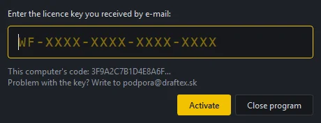
- Enter the key in the form
WF-XXXX-XXXX-XXXX-XXXX. The program adds the hyphens and capital letters itself. - Press Activate. The program connects to the licence server and verifies the key.
- On success a confirmation shows the licence edition, the number of computers and the validity.
Below the field is This computer's code. If you have a problem, send it to support; it identifies you in the records. Support contact: podpora@draftex.sk.
How the licence works
The licence is floating: the key can be installed on up to 20 computers, but only as many workstations run at once as the licence has seats. When the program starts it takes one seat, when it closes it returns it. If all seats are taken, the program shows which computer holds the seat and offers Take over the seat: the other computer locks after 30 seconds and still has time to save its work.
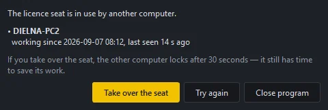
A short internet outage does not interrupt your work. The program keeps running without a connection for 15 minutes; a yellow bar with a countdown and a Try again button appears above the ribbon. After that the tools lock, but saving always works, unfinished work is never lost.
Editions
| Edition | Scope |
|---|---|
| Trial | Full functionality for 7 days. |
| Lite | No PDF export and no artwork (print) tools. The pattern exports to DXF and SVG. |
| Standard | Full functionality. |
| Pro | Full functionality for several workstations. |
Buttons the edition does not allow are greyed out with the tooltip "This function is not in the Lite edition".
Working offline
On site or in a workshop without internet, borrow the licence: on the start screen click Download licence (work offline). The program has to be online at that moment. The loan lasts 7 days; during that time the seat is not released for other computers. The start screen shows how many days remain, in red when two or fewer are left. Back online, click Switch to online; the loan is returned and the seat is released. When the loan expires, the program simply asks for an online seat at the next start.

Managing the licence
Settings → Licence shows the licence number, product name, owner, licence edition and validity.
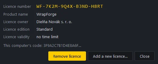
- Add a new licence… replaces the current licence with a new one. The seat on the old licence stays taken until you remove it.
- Remove licence frees the installation seat. At the next start the program asks for the key again. Use it when uninstalling the program or moving it to another computer.
Updates
At start the program checks whether a new version is available. If so, it shows a window with the version number, the list of changes and the download size.
- Update now downloads only the changed files (usually a few MB), Windows asks for administrator consent, the program is assembled next to the old version and restarts. The old version stays working until the new one is complete.
- Later postpones the update. The offer repeats at the next start.
If the update fails, the program continues in the old version and tries again next time.
Program settings
The Settings menu has five windows.
- Display: the colour of the work area and the material gloss in the 3D view. Changes apply immediately.
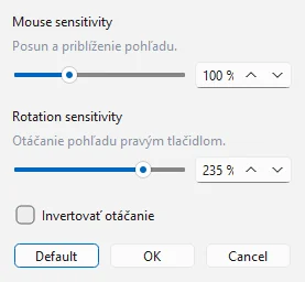
- Controls: Mouse sensitivity (pan and zoom), Rotation sensitivity (right button) and Invert rotation. Default restores the original values.
- Units: Metric (mm) or Inches (in). Switches how dimensions are shown; internally the program always works in mm.
- Language: Slovak (SK) or English (EN). Switches immediately, without a restart.
- Licence: see above.
Help and support
Help → User guide (F1) opens this guide in the browser. Help → Support shows the program version and the button Contact support, which opens an e-mail to podpora@draftex.sk and also copies the address to the clipboard.
When reporting a problem, include the program version from this window, the computer code from the Licence window, and attach the .wfg project or the scan where the problem occurs.
2 Program interface
WrapForge has one main window that switches between three stations. Each station is one phase of the work: first the 3D scan is cleaned up (Model), then a 2D pattern is made from it and refined (Design), and finally the pattern is saved for production (Export). The controls change when you switch station, the window layout stays the same.
Start screen
After launch a start screen appears with two tiles and a list of recently opened files.
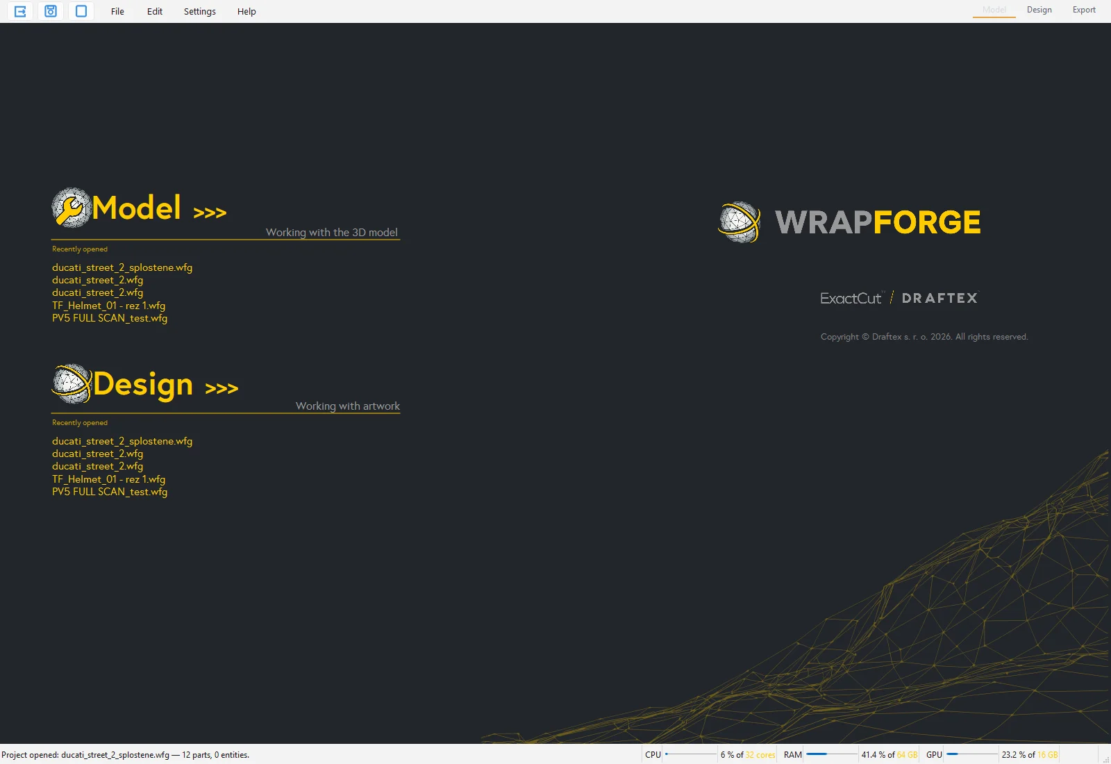
- Model opens a file and switches to the Model station (working with the 3D model).
- Design opens a file and switches straight to the Design station (working with the 2D pattern and artwork).
- Under each tile is the list Recently opened. A click on a name opens the file in that station.
- Bottom right is the program version, and the bottom row holds the licence status and the button for downloading the licence for offline work (see the chapter Installation and licence).
The start screen disappears after a file is opened or after Esc. It shows again at the next program start. The New session button top left closes all parts and leaves an empty scene.
Main window
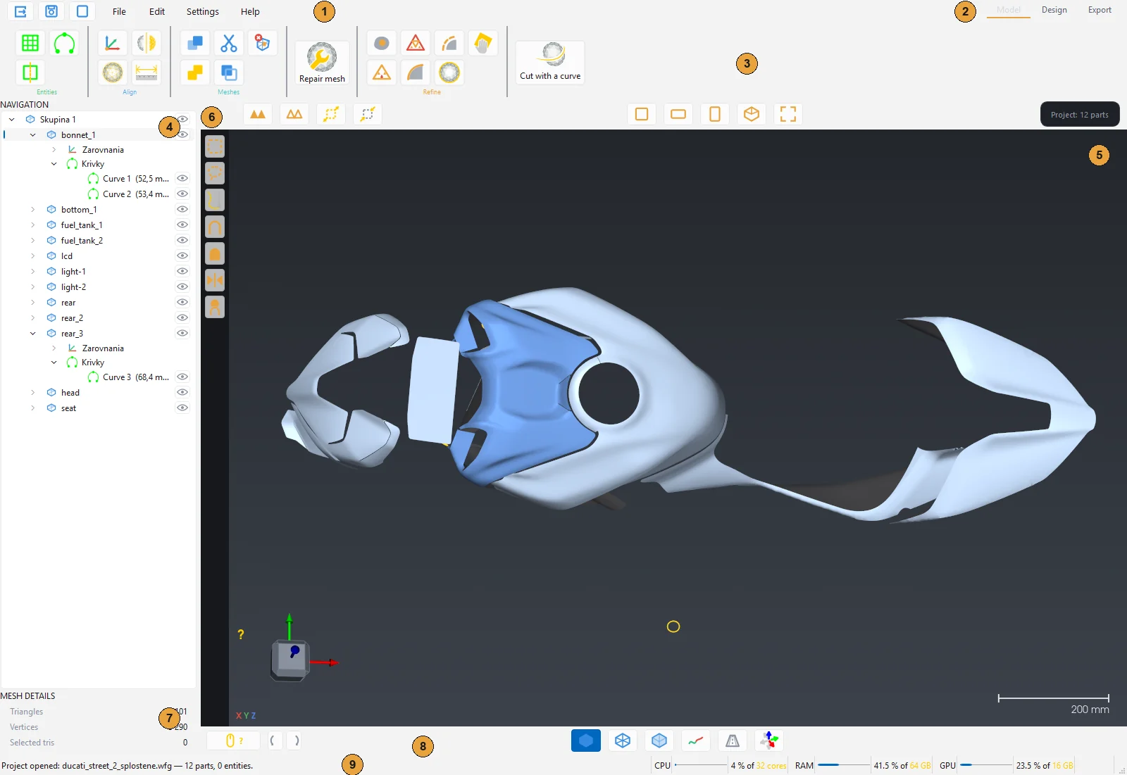
- Menu File, Edit, Settings and Help. Left of the menu are three quick buttons: Open, Save project and New session.
- Station switch Model, Design, Export. The active station has a yellow bar.
- Ribbon with the tool groups of the current station. The tooltip of every icon explains what it does.
- Navigation: the tree of parts, groups and entities (curves, planes, axes). The eye icon toggles visibility.
- Work area: the 3D view. In the Design station it splits into the 2D pattern on the left and the 3D model on the right.
- Left selection bar: rectangle, lasso, brush, curved area, whole part, invert and the Through / Visible only switch. In the Design station the node tools are here.
- Mesh details: the number of triangles, vertices and selected triangles of the selected part.
- Bottom bar: mouse controls help (the yellow button with the question mark), rotate the view by 90°, display modes (shaded, wireframe, transparent), curvature check, perspective and gumball.
- Status bar: program messages and the load of the processor, memory and graphics card.
Tip: When you are not sure what a button does, hold the cursor over it. Every button has a tooltip and every tool panel has its own help under the yellow icon plus a collapsible CONTROLS section.
Three stations

| Station | Purpose | Ribbon contents |
|---|---|---|
| Model | Editing the 3D scan: cleaning, repairing errors, joining, aligning, cutting into parts. | Entities, Align, Meshes, Repair mesh, Refine, Cut with a curve |
| Design | Preparing the mesh, flattening into 2D, strain map, outline editing, artwork, part layout. | Remesh, Flattening, Drawing, Display quality |
| Export | Saving the finished 1:1 pattern to PDF, DXF or SVG. | Export |
Normal work goes left to right: Model, Design, Export. You can switch between stations at any time, nothing is lost.
Ribbon of the Model station

Groups from the left: Entities (plane, part axis, curve), Align (coordinates, best fit, mirror, measurement), Meshes (merge, merge scans, cut out selection, duplicate selection, delete selected triangles), the large button Repair mesh, Refine (fill holes, decimate, rebuild mesh, smooth, smooth boundaries, extend boundaries, sand the surface) and the large button Cut with a curve. Details in the chapter Model station.
Ribbon of the Design station

The large button Remesh, the group Flattening (flattening, Spring, Tension +, Tension −), the group Drawing (point reduction, sander, round corner, cut, canvas, artwork, text, auto-nest, autonest settings, contour, partial contour) and Display quality on the right. Details in the chapter Design station.
Ribbon of the Export station

Three buttons: Export to PDF, Export to DXF and Export to SVG. Details in the chapter Export station.
Menu
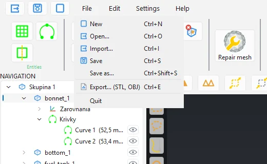
File contains New (Ctrl+N), Open (Ctrl+O), Import (Ctrl+I), Save (Ctrl+S), Save as (Ctrl+Shift+S), Export STL or OBJ (Ctrl+E) and Exit. The difference between Open and Import is that Import also offers IGES curves and does not close the parts already open.
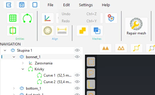
Edit has Undo (Ctrl+Z) and Redo (Ctrl+Y). The item name always says which step will be undone and how many steps remain.
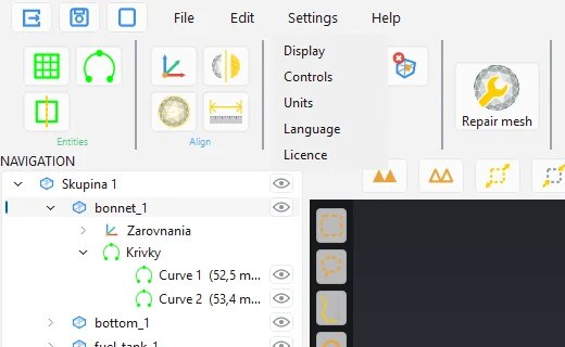
Settings opens the windows Display, Controls, Units, Language and Licence. They are described in the chapters Installation and licence and Controls.
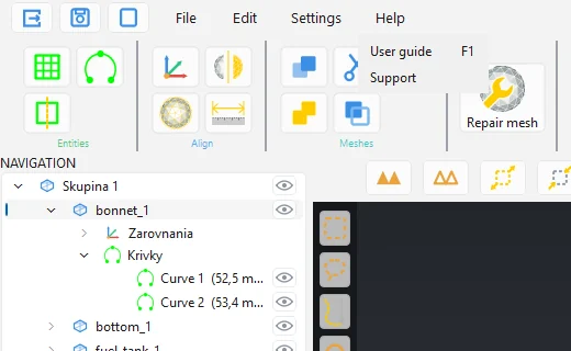
Help contains User guide (F1), which opens this guide in the browser, and Support with the program version and the support contact.
Navigation tree
Every open part is a separate layer in the tree. Parts can be grouped, entities (curves, planes, axes) appear under a part, and with artwork also the image layers.
- Click selects a part. The selected part is the one the tools work with.
- Ctrl+click selects several parts at once (for example for Merge, Merge scans or batch flattening).
- The eye icon hides or shows a part. Hidden parts are ignored by the tools.
- F2 renames a part, Delete deletes it.
- Dragging changes the order and can move a part into a group.
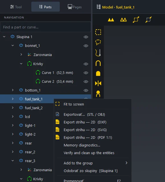
- Right click opens the context menu: Fit to screen, Export (STL/OBJ), Export 2D pattern (DXF, SVG, PDF 1:1), Memory diagnostics, Verify and tidy entities, Create group.
Below the tree are the Mesh details: the number of triangles and vertices of the selected part and the number of currently selected triangles.
Tool panel
Most tools open as a panel in place of the Navigation tree when clicked. While a panel is open the ribbon is dimmed and no other tool can be started.
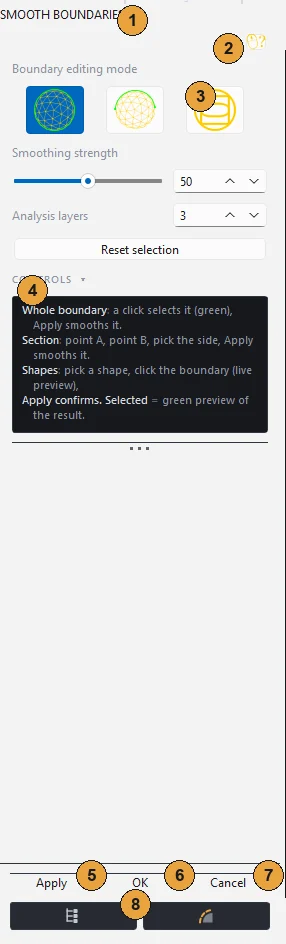
- Title with the tool name. Dragging the title detaches the panel into a separate window.
- Help under the yellow icon: what the tool does and how it is controlled.
- Tool settings: sliders, values in mm, switches.
- CONTROLS: a collapsible overview of the mouse gestures for this tool.
- Apply runs the function with the current settings. It can be pressed repeatedly, for example with another value.
- OK saves the result and closes the panel. If you have not pressed Apply yet, OK runs the function once.
- Cancel returns the part to the state before the panel was opened and closes the panel.
- Layers (the icon bottom left) switches back to the tree so you can hide or show other parts while the tool is open. Return to the panel with Back to the tool.
Note: OK never runs the function a second time. Once you have pressed Apply, OK only confirms what you see in the view.
Work area bars
Top bar (above the 3D view): Select all, Clear the selection, Grow the selection (+), Shrink the selection from the border (−), the Brush size slider, the Edge angle slider and the views Front, Side, Top, Isometric and Whole part. In the Design station this bar holds the layout switches instead (2D only, 2D and 3D, 3D only) and the 2D view modes (wireframe, strain colouring, artwork display, material display).
Bottom bar: the yellow button with the question mark opens the mouse controls overview, next to it are the buttons to rotate the view by 90° left and right, the 3D display modes (shaded, wireframe, transparent), Curvature check, Perspective and Gumball.
Status bar at the very bottom reports what the program has just done or what it expects from you. During longer computations a window with a running bar and a Stop button appears in the middle of the screen. On the right is the load of the processor, memory and graphics card. With large scans watch the memory: when it gets close to full, close the parts you do not need.
Display quality
In the Design and Export stations the ribbon has the Display quality selector on the right: Low, Medium, High, Realistic. It changes the resolution of the artwork (print) preview on the parts. A lower quality frees performance and memory with many images and has no effect on the print export. Low quality also switches off edge anti-aliasing.
3 Mouse and keyboard controls
WrapForge is controlled like a typical 3D program, with one important exception: the view rotates with the right mouse button. The left button is reserved for the tools (clicking points, drawing curves, dragging the brush), so it never rotates the model by accident.
Mouse in the 3D view
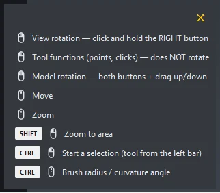
| Gesture | What it does |
|---|---|
| Right button and drag | Rotates the view around the model. |
| Left button | Tool functions (points, clicks, drags). Does not rotate the view. |
| Left + right and drag up/down | Rotates the model around the view axis. |
| Middle button (wheel) and drag | Pans the view. |
| Wheel | Zooms in and out towards the cursor. |
| Shift + left button | Zooms to the selected area. |
| Ctrl + left button | Starts a selection with the tool from the left bar. |
| Ctrl + wheel | Changes the brush radius or the curvature angle. |
The same overview is always at hand: click the yellow button with the question mark in the bottom bar.
Tip: In the menu Settings → Controls you can set the mouse and rotation sensitivity and invert the rotation direction. The Default button restores the original values.
Views and orientation
- The buttons Front, Side, Top, Isometric in the top bar set the view to the standard directions. Whole part zooms to the selected part.
- The axis cube bottom left shows the orientation. Clicking one of its faces turns the view perpendicular to it.
- The buttons in the bottom bar rotate the view by 90° left or right.
- Perspective in the bottom bar switches between perspective and parallel projection. Parallel projection is more accurate for measuring and comparing shapes.
Selecting triangles
Most tools in the Model station work with a selection: a marked part of the surface. Selected triangles are yellow. The selection is made with the tools from the left bar and always starts with Ctrl held down, so it does not interfere with the tool's own work.
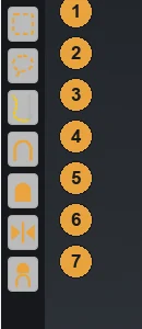
- Rectangle selection: drag a frame in the view.
- Lasso selection: draw around the area freehand.
- Brush selection: drag across the surface. The brush size is in the top bar or via Ctrl + wheel.
- Select a curved area: click the surface; the selection grows from the clicked point and stops at edges where the surface bends more sharply than the set Edge angle.
- Select the whole part: Ctrl + click the part.
- Invert the selection: selected becomes unselected and vice versa.
- Through / Visible only: switched on, it also selects triangles behind the surface (for example the inner side of the scan); switched off, only what is visible. Applies to rectangle and lasso.
The top bar adds Select all (the whole connected piece under the selection), Clear the selection, Grow the selection (+) by about 5 mm and Shrink the selection from the border (−) by about 5 mm. Through is off after start.
With the brush and the curved area, Ctrl+Shift removes from the selection. With the brush, a click and another click with Ctrl held makes a straight line.
Warning: On a dense scan with several layers (for example a panel scanned together with its inner side) select with Through switched off, otherwise the back side is selected too and more is deleted or cut out than you wanted.
Gumball
Gumball in the bottom bar of the Model station switches on handles for moving and rotating the selected parts in all axes. Arrows move along an axis, arcs rotate, the centre moves freely, Ctrl during the drag snaps to 5 mm or 5° steps. It is used for manual alignment of parts. The Artwork tool in the Design station has its own gumball for placing the image.
Mouse in the 2D view (Design station)
In the 2D view with the pattern the view does not rotate, it only pans (middle or right button) and zooms (wheel). The left button serves the tools:
- Click on a part selects it, drag moves it, the yellow arrows in the corners rotate it.
- Ctrl + click adds or removes a part from the selection, a frame over the empty area selects several parts.
- In the node editor a click selects a node, a drag moves it, a frame selects several nodes and the handles bend the curve.
- The yellow splitter between the 2D and 3D views can be dragged and changes the ratio of the views.
Keyboard shortcuts
| Shortcut | Function |
|---|---|
| Ctrl+N | New (closes all parts) |
| Ctrl+O | Open |
| Ctrl+I | Import |
| Ctrl+S | Save project |
| Ctrl+Shift+S | Save as |
| Ctrl+E | Export part (STL, OBJ) |
| Ctrl+Z | Undo |
| Ctrl+Y, Ctrl+Shift+Z | Redo |
| F1 | User guide |
| F2 | Rename the part in the tree |
| Delete | Delete the part in the tree, the selected triangles, the selected nodes or curve points |
| Enter | Finish the cut (Cut tool) |
| Esc | Cancel the tool, gesture or selection |
Undo and redo
Every change to the mesh, the pattern or a part's position is a step that can be undone with Ctrl+Z. The Edit menu shows exactly what will be undone and how many steps remain. While a computation is running, a step cannot be undone; the program says so in the status bar.
Note: Undo keeps a copy of the mesh in memory for large scans. If memory is running out, save the project and close the parts you have finished with.
4 Model station
In the Model station the scan is prepared for flattening: scan errors and debris are removed, several scans are joined, the part is aligned and cut into pieces that can be unfolded into a plane. All tools of this station work with the 3D triangle mesh.
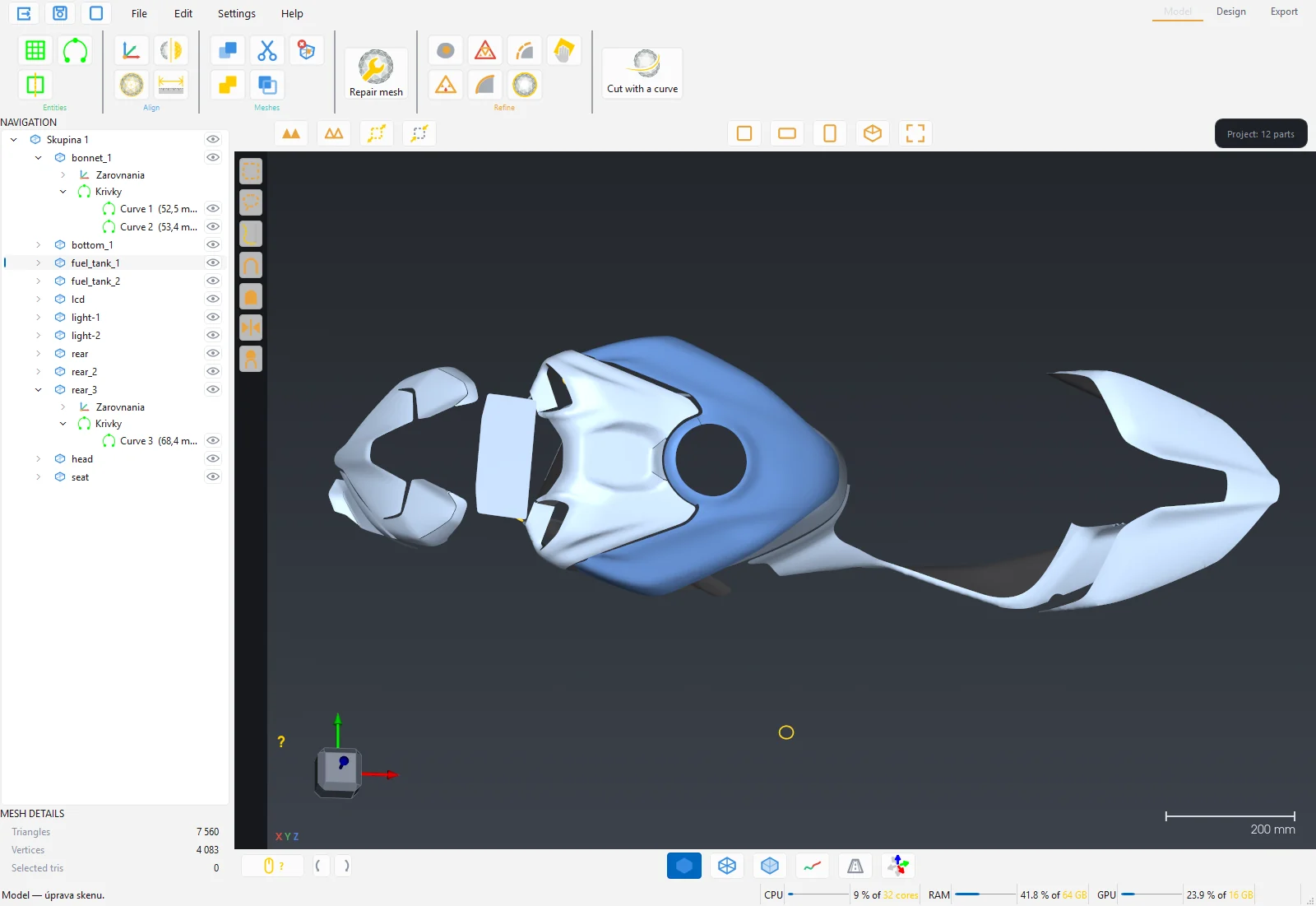
Opening a scan
File → Open (Ctrl+O) opens a 3D mesh in STL, OBJ or PLY format, a .wfg project or a DXF or SVG cutting file. File → Import (Ctrl+I) adds a file to the parts already open and additionally accepts IGES curves. Loading a large scan takes several seconds to minutes depending on its size; a window with a running bar shows the progress.
After loading, the part appears in the Navigation tree and in the 3D view. Below the tree you see the number of triangles and vertices.
Tip: Keep scans on a local SSD, not on a network drive. A full-body scan of 2 GB needs 20 to 30 GB of memory while loading.
Typical workflow
- Repair mesh: remove spikes, islands, small holes and other scan errors.
- Fill holes: patch larger openings the scan did not capture.
- Optionally Merge scans of the same part or Best fit onto a reference part.
- Cut with a curve: split the part into pieces where the seam of the film or fabric will be.
- Switch to the Design station.
The other tools (smoothing, decimation, sanding, mirroring, measurement) are used as needed.
Entities group
Entities are helper objects under a part in the tree: planes, axes and curves. They are used for mirroring, alignment, marking in the pattern and export to CAD.
Plane
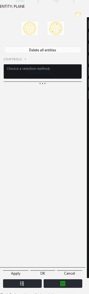
A plane fitted through points or a surface area on the part. It serves as a mirror axis or as a marking line in the pattern (after flattening, the trace of the plane appears as a yellow curve).
- Mode Surface: hold Ctrl and mark an area (rectangle, lasso or brush). When you release Ctrl, a plane fitted through the marked area is created.
- Mode Points: Ctrl+click at least 3 points on the surface. The table shows the coordinates and deviation of each point; Delete selected points removes them.
- After the plane is created, the Parameters appear: Length, Width, Rotation, Offset X, Offset Y and Flip normal. The plane can also be edited by dragging the gizmo in 3D.
- Apply confirms the plane and keeps the mode on for the next one. OK saves all planes under the part, Cancel discards all planes created since the tool was opened.
You can edit a plane later by double-clicking it in the tree.
Part axis
A least-squares line through the centres of the selected planes (at least two). Tick the planes in the list and press Apply. The axis opens for editing with a gizmo: arrows move, the ring rotates, the dots change the size.
Curve
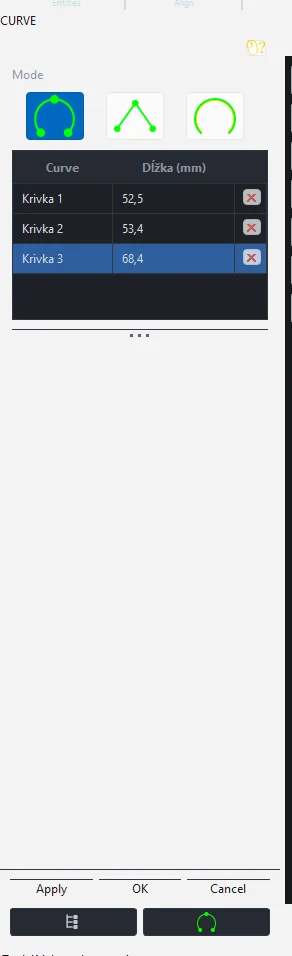
Curves drawn on the surface appear in the pattern after flattening as marking curves (yellow, exported to the KRIVKY layer) and can be exported to IGES.
- Spline: a smooth curve through the clicked points. A double click makes a corner (fixed point), Esc returns to the last corner.
- Polyline: a broken line through the clicked points.
- Extract boundaries: curves from the boundaries of the mesh. A click on a green boundary selects it.
- Apply saves the drawn curve into the table (min. 2 points), OK writes all curves under the part into the Curves node. The table shows the length of each curve; ✕ removes it.
Align group
Coordinates
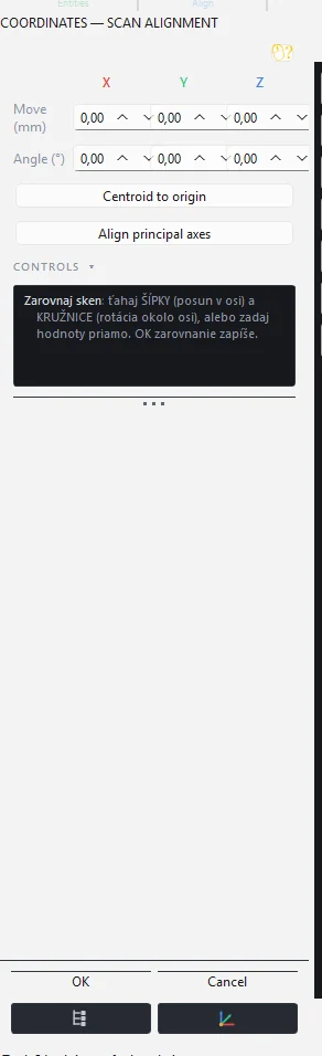
Aligns the scan to the coordinate system. Drag the arrows (move along an axis) and circles (rotate around an axis) in 3D, or enter Offset and Angle directly for X, Y, Z. Centroid to origin moves the centre of the scan to 0,0,0. Align principal axes turns the scan according to its main directions. Both buttons only pre-fill the values; OK writes them. The panel has no Apply so that the alignment is not added twice. With a group, all members are aligned.
Best fit
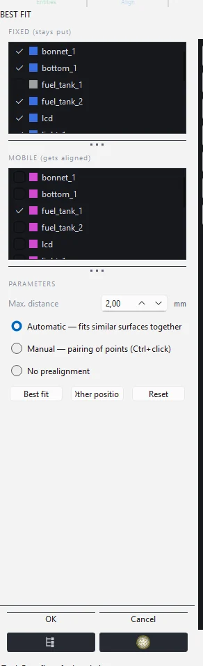
Fits one part onto another, for example a new scan onto a reference one, or the left fender onto the mirrored right one. The scene must contain at least two parts.
- In the list Fixed (stays) tick the part that does not move. In the list Moving (is aligned) there is always exactly one part.
- Max. distance (default 2 mm) sets how far apart points of the two parts may be to count as the same surface.
- Pre-alignment: Automatic matches similar surfaces on its own. Manual requires point pairing: Ctrl+click a point on the moving part, then on the fixed part, at least 3 to 4 pairs. None starts from the current position.
- Press Best fit. The panel reports the deviation and the match percentage. If the automatic guess is wrong (for example the opposite end of the vehicle), Other position switches to the next candidate. Reset clears it.
- OK writes the position into the mesh.
Mirror
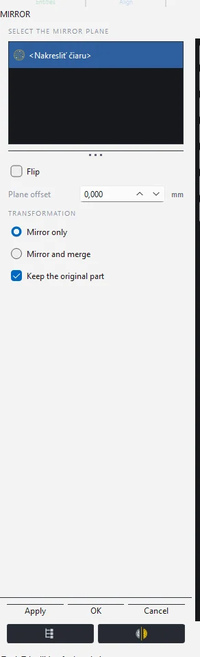
A mirror image of the part across a plane, for example the right fender from the left one.
- In the list choose the mirror plane: Draw a line (hold Ctrl, click point A, click point B in 3D), an existing plane entity of the part, or the group plane (the whole group is mirrored).
- Flip swaps the side of the plane, Plane offset moves it in mm.
- Mirror only creates a mirror image of the whole part. Mirror and merge takes the half of the part on the normal side and completes it with its mirror (symmetrisation).
- Keep the original part leaves the original and adds a layer with the suffix "-zrkadlo".
- Apply mirrors and consumes the plane (another mirroring needs a new one), OK closes.
Measurement
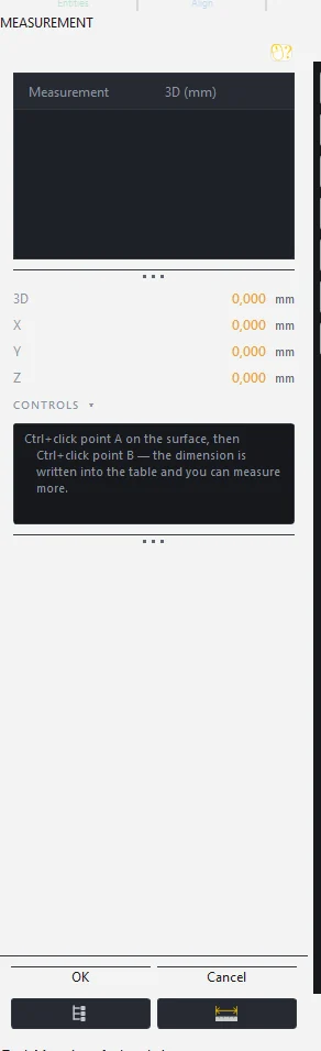
The distance between two points on the surface: Ctrl+click point A, Ctrl+click point B. The dimension goes into the table with the 3D distance and the X, Y, Z components. OK saves the dimensions under the part in the Measurements node, Cancel discards them.
Meshes group
Tools for several parts and for working with the triangle selection. Select several parts with Ctrl+click in the tree.
- Merge: welds the meshes of the selected parts (at least two) into one new layer "spojené". The originals stay.
- Merge scans: permanently joins the selected parts into one mesh and repairs it. For parts lying on top of each other (pieces of one mesh) the result is immediate. For overlapping scans the Merge scans panel opens, see below.
- Cut out selection: makes a new layer with the suffix "-odstrih" from the selected triangles and removes them from the part.
- Duplicate selection: makes a new layer "-výber" from the selected triangles; the original part stays whole.
- Delete the selected triangles: removes the selection from the mesh.
Merge scans
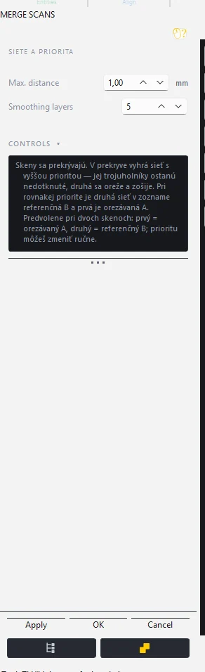
When two scans of the same part taken from different sides share an overlap, the panel stitches them into one mesh. In the overlap the mesh with the higher priority (Low, Normal, High) wins: its triangles stay untouched, the other one is trimmed and stitched on. By default the first part is trimmed and the second is the reference.
- Max. distance: how far apart two surfaces may be to count as the same surface. Anything farther stays separate.
- Smoothing layers: how many rings around the seam are smoothed so that no step remains on the seam.
- After opening, the panel reports the overlap percentage and the distance between the surfaces and suggests a distance. With a large distance do a Best fit first.
- OK merges; the result is a new layer, the originals disappear. One Undo step restores everything.
Repair mesh
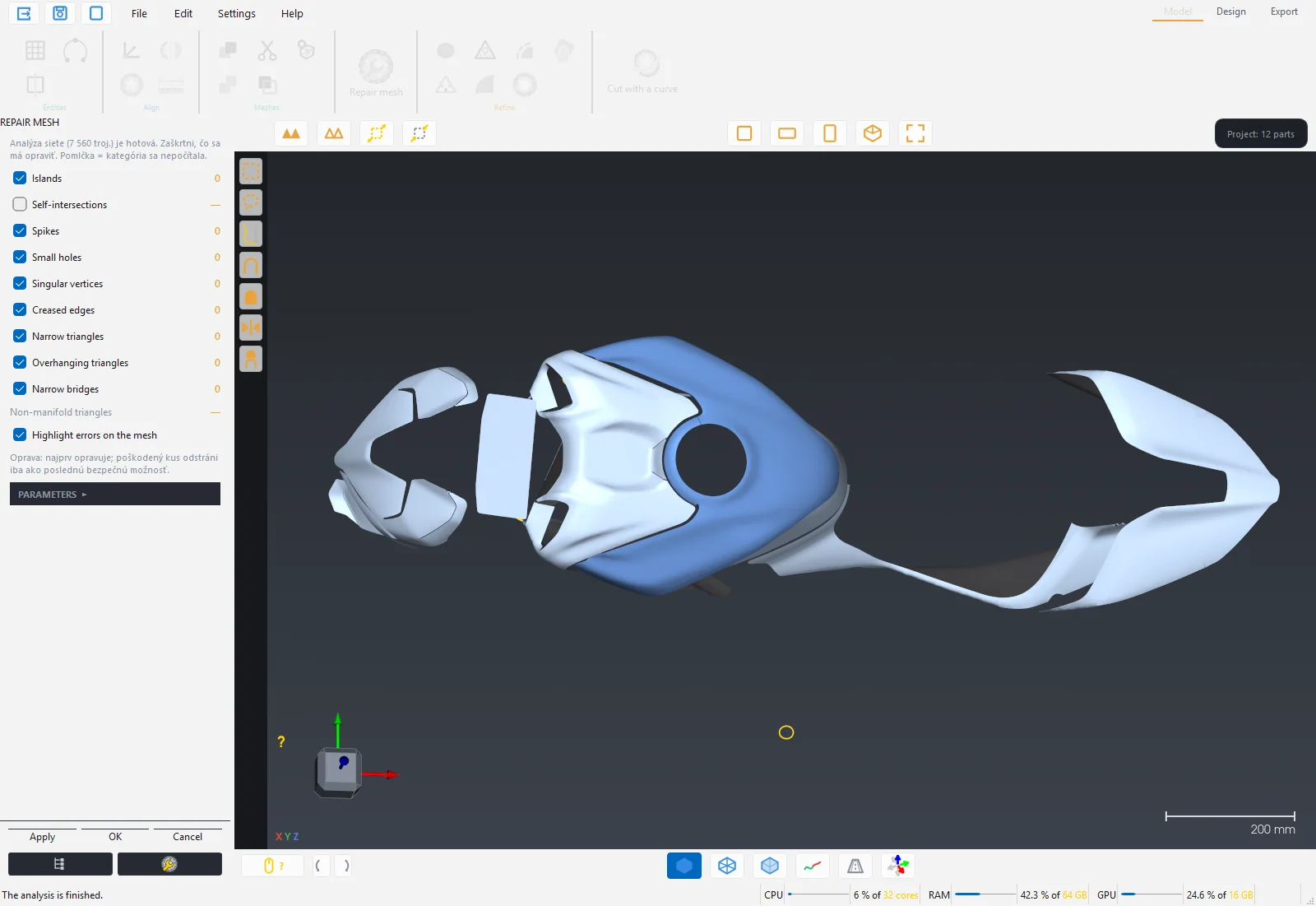
Mesh error analysis. The program finds the errors and you decide what is repaired. If an area is selected on the part, only that area is repaired, otherwise the whole part.
| Category | What it is |
|---|---|
| Islands | Small detached pieces of the scan away from the part. |
| Self-intersections | Places where the mesh passes through itself. Computationally expensive; while the box is unticked the category is not computed. |
| Spikes | Isolated pulled-out vertices, scan noise. |
| Small holes | Tiny unclosed openings. |
| Singular vertices | Vertices that hold two pieces together by a single point. |
| Creased edges | Sharp bends above the set angle. |
| Narrow triangles | Needle-like faces that spoil the computation. |
| Overhanging triangles | Faces sticking out of the surface. |
| Narrow bridges | Thin connections between two otherwise separate surfaces. |
- After opening, the analysis runs and a count appears for each category. Highlight errors on the mesh colours them red directly on the part.
- Tick what should be repaired. By default everything except self-intersections is ticked.
- The Parameters section hides the thresholds: island size, spike level, crease angle, bridge width and maximum hole size. The Preview button recounts with the new thresholds.
- Apply repairs and immediately runs a check analysis. OK saves and reports what remained unrepaired. Cancel restores the original mesh.
Note: The repair repairs first; it removes a damaged piece only as the last safe option. With an error-free mesh OK changes nothing.
Refine group
Fill holes
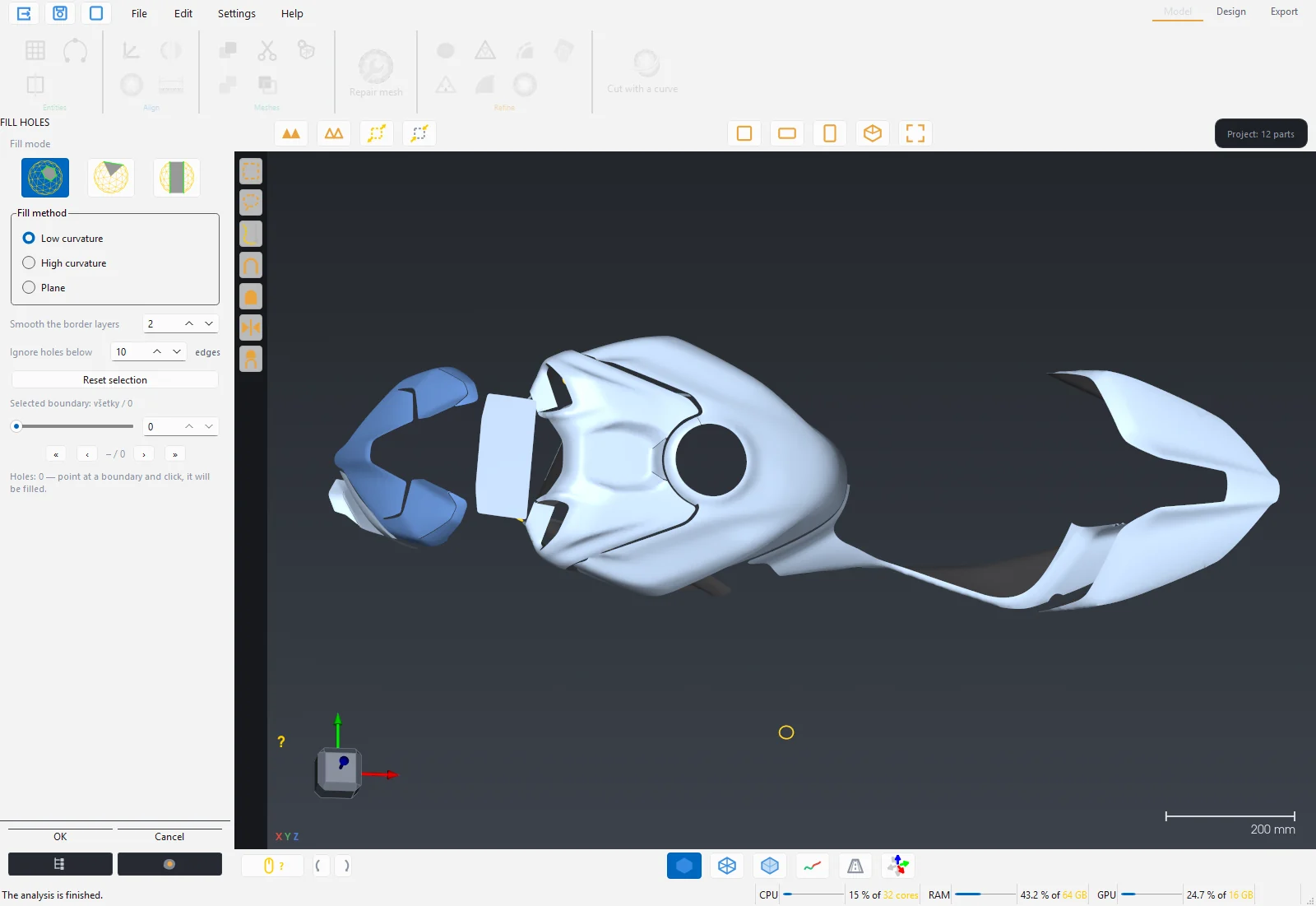
After opening, the program finds all holes (boundaries without neighbours) and highlights them. Holes smaller than Ignore holes below (default 10 edges) count as noise and are not shown.
- Whole hole: a click on the boundary fills the hole immediately. The slider or arrows step through the holes one by one; the value 0 means all at once.
- Partial fill: click 2 points on the boundary and then the side that should be filled (a green arc and chord show the segment). Used for large openings where only a part needs patching.
- Bridge: joins two meshes. 2 points on the boundary of the first part, a click on the curve between them, 2 points on the second part, a click on its curve. The parts are joined, the second one disappears.
- Fill method: Low curvature for flat surfaces, High curvature for domed ones (only with Whole hole), Plane.
- Smooth the border layers smooths the transition of the patch into its surroundings.
- OK saves, Cancel restores the mesh.
Decimate
Reduces the number of triangles to the given percentage (default 50 %). Useful for a quick preview or a lighter part. Keep boundaries holds the boundary vertices in place so the outline is not deformed. Decimation always starts from the original, so repeated Apply with another value does not accumulate.
Rebuild mesh
A uniform mesh with the boundary preserved and good-quality triangles. Target vertices is pre-filled with a tenth of the current count, Adaptive refinement of radii densifies the mesh in curves. Remesh in the Design station does the same work with batch processing of several parts; this panel is handy when you want to rebuild the mesh before cutting.
Smooth
Removes scan noise and keeps the volume. Smoothing strength (Low, Medium, High), Iterations, Keep details (percentage), Keep boundaries and Sharpen (adds the detail back after smoothing). If an area is selected on the part, only that area is smoothed.
Smooth boundaries
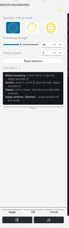
The edge of a scan tends to be jagged. This tool smooths it or replaces it with an exact shape.
- Whole boundary: a click selects the boundary (green), Apply smooths it with the force from Smoothing strength.
- Boundary segment: point A, point B, side selection, Apply smooths only the segment.
- Basic shapes: choose Circle, Square / rectangle or Oval (ellipse) and click the boundary, for example a screw hole or a mounting opening. A live preview shows the result, Apply confirms.
- Analysis layers sets how many rows of triangles from the edge are taken into account.
Extend boundaries
Adds a strip of mesh of the given Length (default 5 mm) to the edge of the scan, for example when the scan ends right at the edge of the part and the film should go around it. A click on the boundary shows a yellow translucent extension, Apply adds it. The partial mode adds the extension only on a segment (point A, point B, side). Boundary smoothing sets how many layers of the transition are smoothed.
Sand the surface
Sandpaper for the scan: Ctrl shows the brush circle, Ctrl+left drag sands and smooths, Ctrl+wheel changes the radius. Sanding strength, Radius, Keep features (distinct edges and creases are sanded gently) and Keep boundaries. OK keeps, Cancel restores. Works on parts up to 8 million triangles; cut or decimate a larger part first.
Cut with a curve
The most important tool of the Model station. A closed shape (for example a whole bonnet or helmet) cannot be unfolded into a plane without a seam. Cut with a curve splits the part into pieces along curves drawn on the surface exactly where the seam of the film or fabric will be.
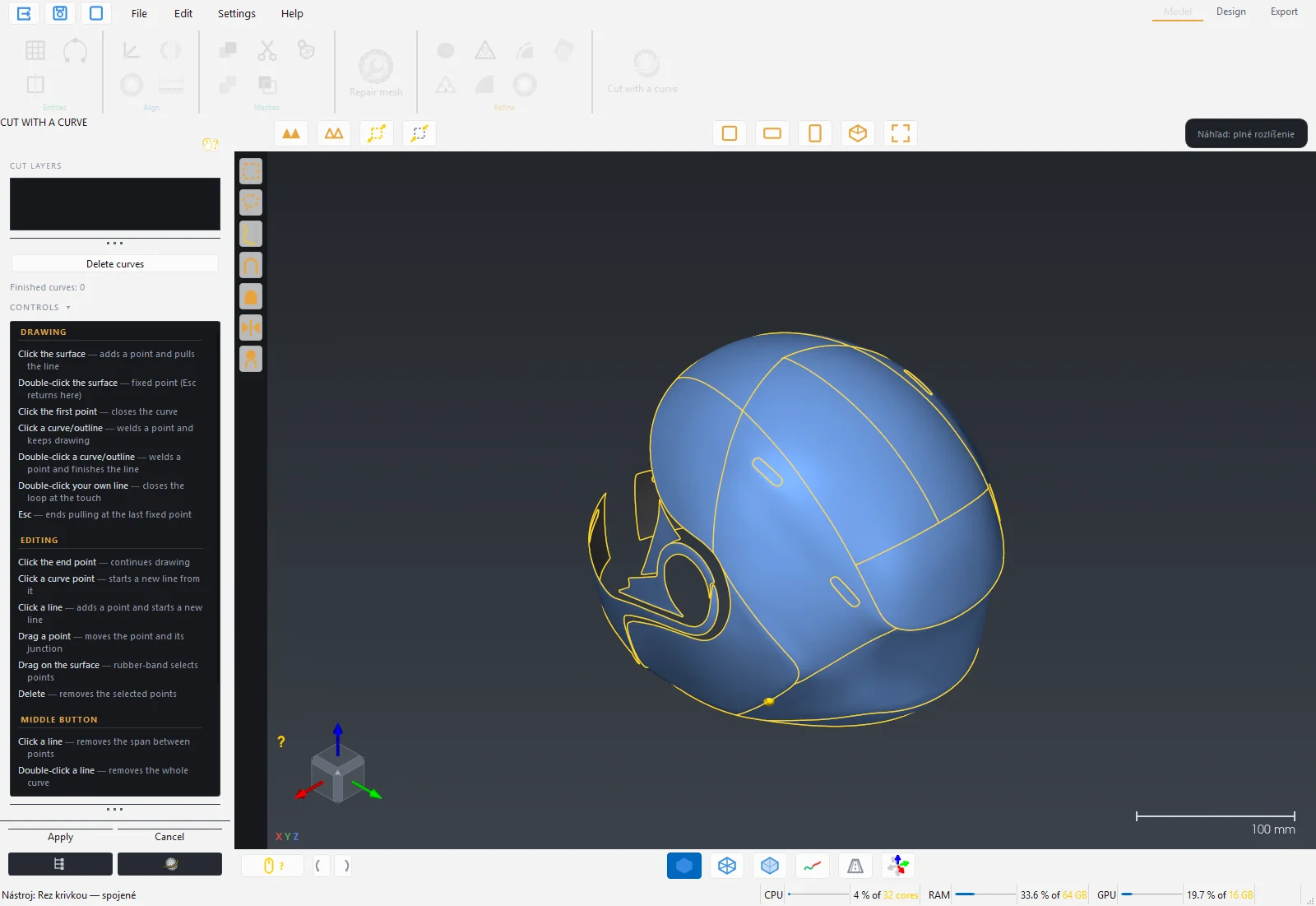
Drawing curves
| Gesture | Effect |
|---|---|
| Click on the surface | Adds a point and continues the line. |
| Double click on the surface | Fixed point. Esc returns here. |
| Click on the first point | Closes the curve. |
| Click on a curve or the outline | Welds a point and continues drawing. |
| Double click on a curve or the outline | Welds a point and ends the line. |
| Double click on your own line | Closes a loop at the touch. |
| Esc | Ends dragging back to the fixed point. |
A curve is finished when it is closed or when both ends lie on the outline of the part or on another curve. An unfinished curve with a free end is red.
Editing curves
| Gesture | Effect |
|---|---|
| Click on an end point | Continues drawing. |
| Click on a curve point | Starts a new line from there. |
| Click on a line | Adds a point and starts a new line. |
| Drag a point | Moves the point and its connection. |
| Drag into the surface | Drags the points into the selection. |
| Delete | Deletes the selected points. |
The middle button deletes: a click on a line deletes the segment between points, a double click on a line deletes the whole curve, a click on a point deletes the point, a click on the outline of the part switches it off (a double click restores it). The cursor on a line shows in green which segment will be deleted. The right button rotates the view, the wheel zooms towards the cursor.
Creating the layers
- Press Apply. The program cuts the part and shows a coloured preview of the layers. The list Cut layers with tick boxes appears in the panel.
- Untick the layers you do not want (they are translucent in the preview). A right click on an item renames it.
- OK creates the layers from the ticked items and removes the original part. One Undo step restores everything.
- A click into the scene or Esc returns you to curve editing, Delete curves starts over.
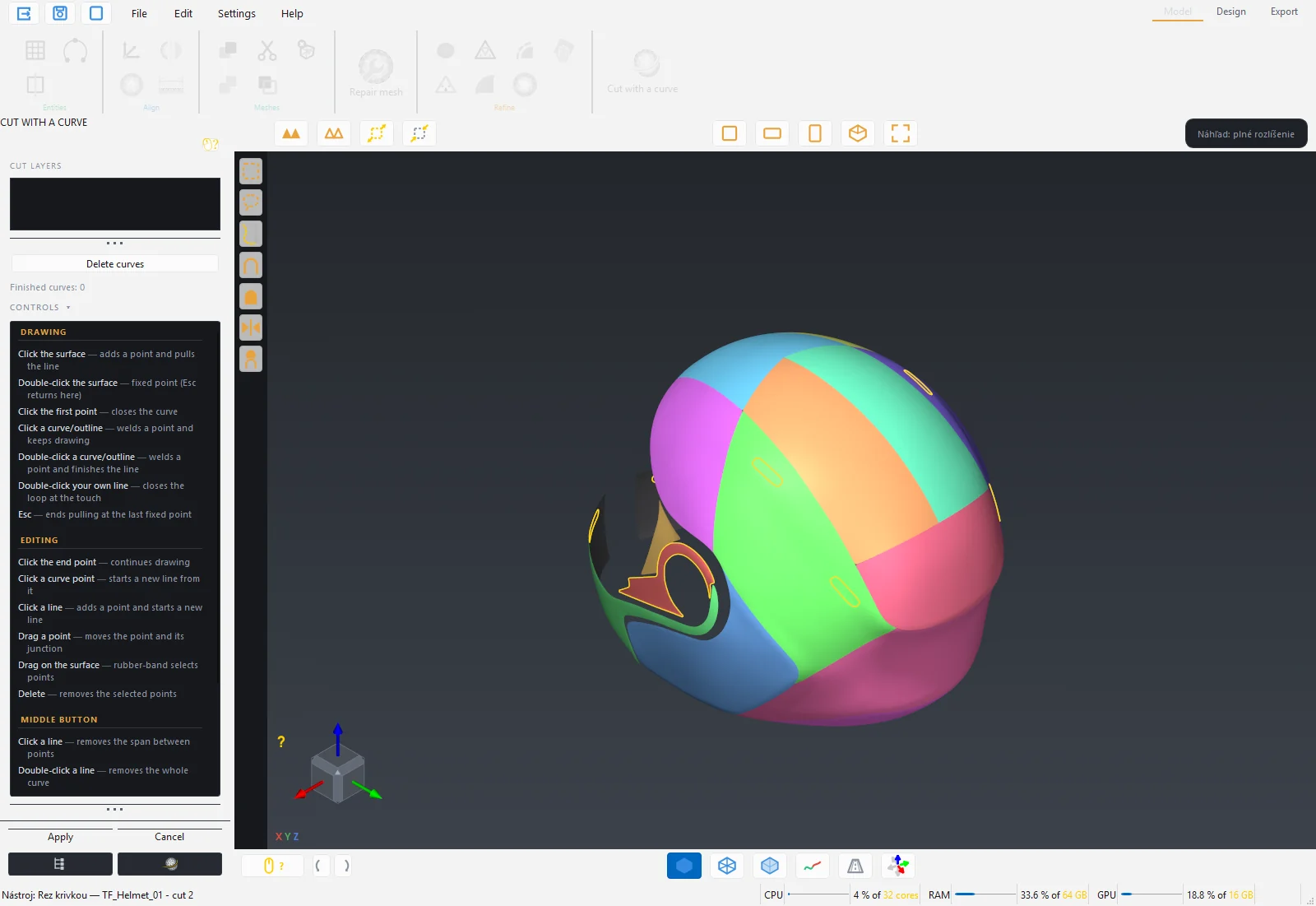
Tip: Route the seam where it is least visible: along edges, creases and lips. Choose the pieces so that each is only mildly domed. A piece that is too convex shows red or black areas in the strain map after flattening.
Gumball
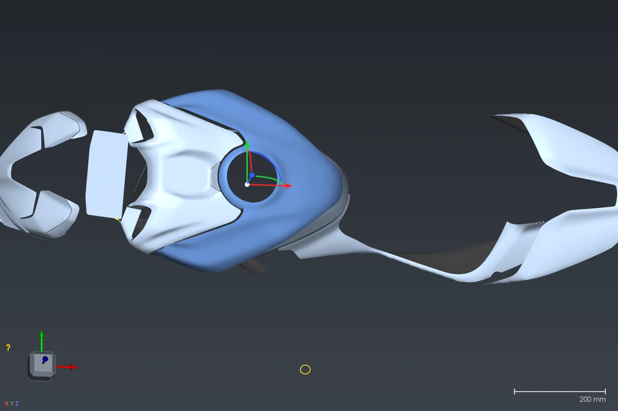
Gumball in the bottom bar switches on handles on the selected parts: arrows (red X, green Y, blue Z) move along an axis, the white ball moves freely in the screen plane, the coloured arcs rotate around an axis. Ctrl during the drag snaps to 5 mm or 5°. On release the position is written into the mesh; Undo restores it. The gumball is in the Model station; in Design the Artwork tool has its own gumball.
5 Design station
In the Design station the cleaned-up 3D part becomes a 2D pattern. The workflow always has the same order: Remesh prepares the mesh, Flattening unfolds it into a plane, optionally Spring accounts for the film material, then the outline is refined, artwork is added and the parts are laid out on the material. The status bar reminds you of this order when you switch to the station.
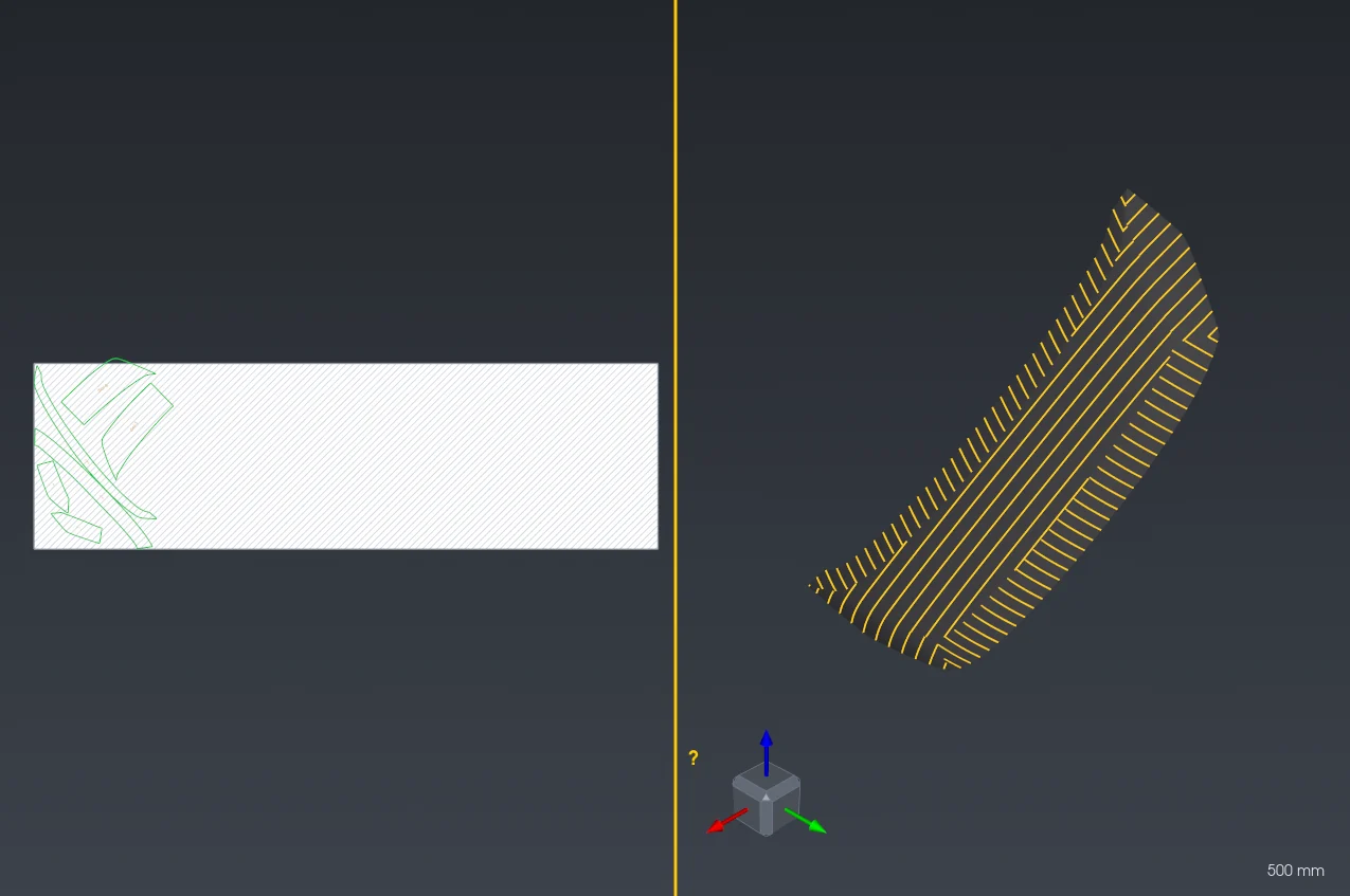
In Design the window splits: on the left is the 2D pattern on a white work area, on the right the 3D model. The yellow splitter between them can be dragged; the switches in the top bar show 2D only, both views or 3D only.
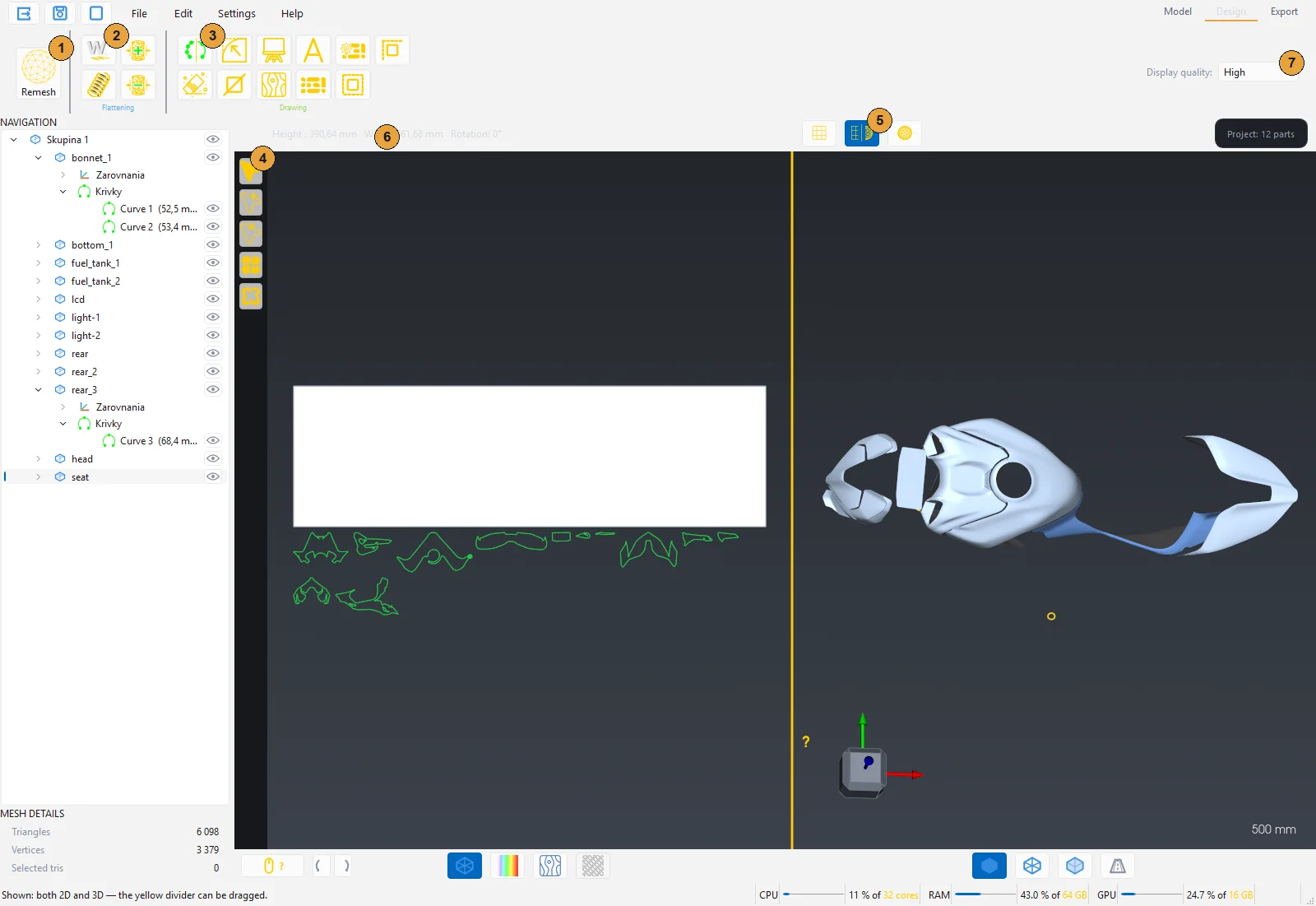
- Remesh, the first step for every part.
- The Flattening group: Flattening, Spring, Tension +, Tension −.
- The Drawing group: outline editing, Canvas, Artwork, Text, Auto-nest, Contour.
- Node tools in the left bar: Nodes, Add node, Remove node, Group, Ungroup.
- View layout and 2D modes: wireframe, strain colouring, artwork display, material display.
- Dimensions of the selected part in 2D: Height, Width and Rotation.
- Display quality of the artwork preview.
Remesh
Flattening accepts only parts that have been through Remesh. Remesh rebuilds the scan mesh into a uniform, good-quality mesh with the boundary kept exactly. A scan typically has hundreds of thousands to millions of triangles of uneven size; a few thousand uniform vertices are enough for flattening.
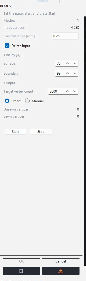
- Select the part in the tree (or several with Ctrl+click, or click a group) and press Remesh.
- If the mesh has errors, the program asks whether to repair them first. We recommend Yes: a remesh on a damaged mesh tends to fail.
- Set the Target vertex count (default 3000) and leave the mode at Smart.
- Press Start. The result appears directly in the 3D view as a preview.
- When you are satisfied, press OK. The panel confirms it in the status bar.
| Setting | Meaning |
|---|---|
| Sew tolerance [mm] | How close two points must be to count as the same point. Default 0.25 mm. |
| Delete input | On: the remesh overwrites the mesh of the original layer; the part stays in place in the tree and in its group. Off: the result is added as a new layer with the suffix "- remesh". |
| Target vertex count | Density of the resulting mesh. Larger and more detailed parts need more; a typical body panel 3000 to 8000. |
| Smart | When the given count does not give a usable pattern, the remesh finds the nearest working count itself and reports it. |
| Manual | Remesh to exactly the given count, without searching for another. |
Tip: A lower vertex count means faster flattening and a smoother outline; a higher count follows small creases and sharp corners more faithfully. If the outline looks simplified after flattening, repeat Remesh with a higher count.
The Stop button halts a running computation, Cancel restores the original meshes. When finished, the program reports how many parts succeeded and how many failed. A part that fails at every vertex count is usually damaged: go back to the Model station and run Repair mesh.
Flattening
Flattening unfolds the remeshed part into 2D. It has no panel: select the part (or several parts) and press Flattening. During the computation a window with a bar and a Stop button runs.
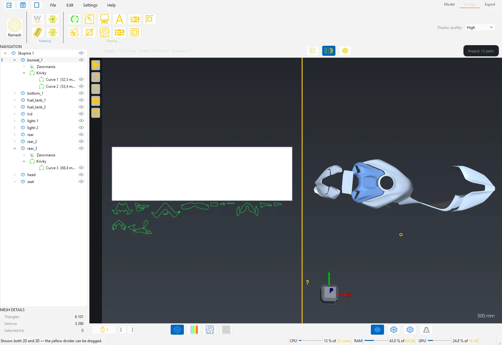
When it finishes:
- The outline of the part appears in the 2D view as a solid green line. Parts are placed below the white work area like a parking lot; place them on the area by hand or with Auto-nest.
- Marking curves (curves from entities or plane traces) are yellow. They export as marking, not as cuts.
- The top bar shows the Height, Width and Rotation of the selected part in 2D.
- The status bar reports the maximum stretch and compression in percent and whether the pattern contains flipped polygons.
Flipped polygons are places where the surface folded over itself during unfolding. The program shows them as dark crosses. If they appear, the part is too curved for one piece: go back to the Model station, split it with Cut with a curve into several parts and repeat Remesh and Flattening.
Warning: Flattening can also run on several selected parts at once. Parts that have not been through Remesh are skipped and their names are listed.
Strain map
The Strain colouring switch in the top bar colours the parts according to how much the film has to stretch or compress when applied. The same colouring is projected onto the 3D model. A vertical legend appears on the right.
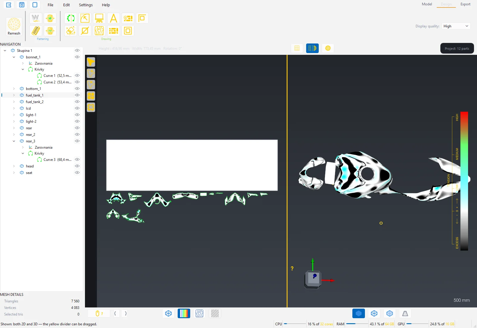
| Colour | Meaning |
|---|---|
| White | No strain, the film fits exactly. |
| Cyan, green, yellow | Increasing stretch. The film is stretched at this point. |
| Red | Maximum stretch. The limit for ordinary films. |
| Black | Excess material. The film has to be compressed here or it wrinkles. |
After flattening the scale is in percent of area deformation. After Spring it switches to N/m (force per metre of material width). Large red or black areas mean the part should be cut into more pieces or the seam position changed.
Spring
Spring refines the 2D shape according to the properties of the specific film: how it stretches lengthwise and crosswise and how it holds its shape. The result is a pattern that fits better after application than a purely geometric unfolding, plus a strain map in N/m.
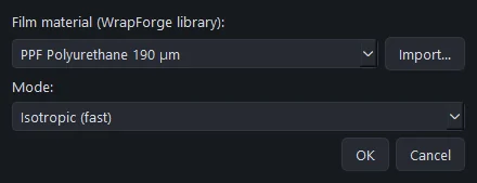
- Select a flattened part and press Spring.
- Choose the Film material from the library. The program ships for example a cast film with lamination and PPF 190 µm.
- Choose the Mode: Isotropic (fast) assumes the same properties in all directions, Orthotropic (fiber direction) distinguishes the winding direction and the cross direction.
- Press OK. After the computation, Strain colouring switches on automatically.
Add your own material with the Import… button. The New material window opens with the fields Name, Tensile modulus (isotropic), Tensile modulus in the winding direction and in the cross direction, Shear modulus, Poisson's ratio and Film thickness. The moduli are entered in N/m (force per metre of width), not in MPa. You get the values from the film manufacturer or from a tensile test. The material is saved in the library and next time you pick it by name.
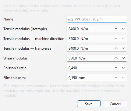
Note: Spring requires a pattern without flipped polygons. If the pattern has them, the program says so. Repair the mesh or cut the part and run Flattening again.
Tension + and Tension −
When applying, the film is deliberately stretched on convex spots. Tension + accounts for this: the part shrinks in the direction of the drawn line (the material is stretched during application) and widens perpendicular to it according to the material properties so it does not get narrower. Tension − does the opposite: the part lengthens in the direction of the line and narrows perpendicular to it.
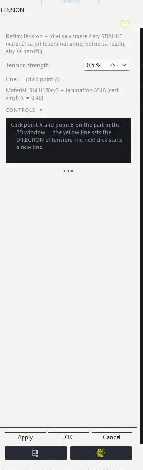
- Select a flattened part and press Tension + or Tension −. Strain colouring switches on.
- In the 2D view click point A on the part and then point B. The yellow line between them sets the direction of the tension.
- Enter the Tension strength in percent (default 0.5 %).
- Press Apply. The status bar reports how the part changed along the line and perpendicular to it.
- The next click starts a new line. OK closes the panel, Cancel restores the original shape and strain map.
The panel also shows the material used and its Poisson's ratio, which sets the ratio between shrinking and widening.
Outline editing
The outline of the pattern is a smooth curve with nodes. It can be edited by hand in the node editor or with the tools Point reduction, Sander, Round corner and Cut. All of them work in the 2D view with the flattened part.
Node editor
In the Design station the left bar holds the node tools.
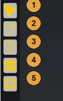
- Nodes: a click selects a node, Ctrl adds to the selection, a drag moves the node, a frame selects several nodes. The selected node has handles that bend the curve. Ctrl on a handle turns the node into a corner.
- Add node: click the outline.
- Remove node: click the node or use a frame. The outline must keep at least 3 nodes.
- Group: locks the selected parts so they move together in 2D. It is a temporary lock; it is not saved in the project and does not change the groups in the tree.
- Ungroup: releases the lock. With a selected node of a plane trace it detaches the trace as a separate curve that can be moved in 2D.
The node tools cannot be switched on while another panel runs (Tension, Point reduction, Sander, Round corner). Close it first with OK or Cancel.
Point reduction
A flattened outline has many nodes. Point reduction keeps the smallest possible number of nodes so that the line does not deviate from the original by more than the set deviation. Corners and small radii hold on their own.
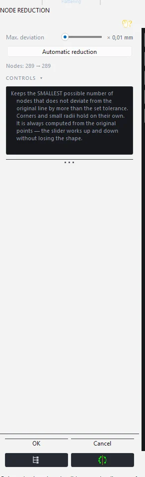
- The Max. deviation slider is in hundredths of a millimetre: 0 keeps all points, 5 is 0.05 mm (cutting precision), 100 is 1 mm. It is always computed from the original points, so the slider works up and down without losing shape.
- Automatic reduction sets the smallest number of nodes at the cutting precision of 0.05 mm.
- The Nodes row shows the original and the current count.
- OK confirms, Cancel restores the original state.
Sander
The Sander works like a sanding block on the outline: dragging the brush along the line straightens a wavy segment into a straight line, tightens an uneven circle into a true circle and removes redundant nodes. Sharp corners stay.
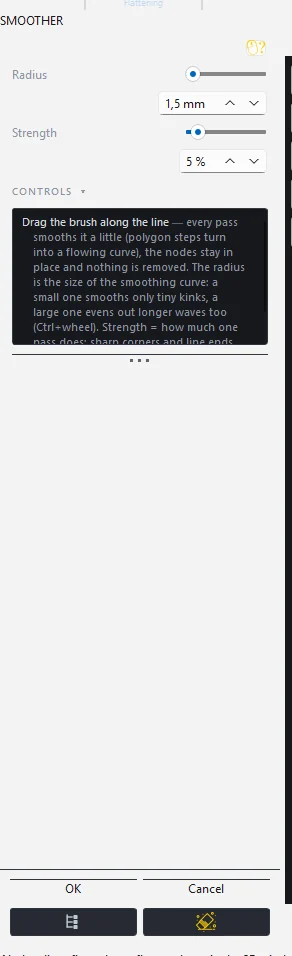
- Set the brush Radius in the panel or with Ctrl + wheel in the 2D view. The brush evens out waves shorter than its width; use a larger radius for a larger unevenness.
- The effect is applied directly while dragging. OK confirms, Cancel restores the outline from before the panel was opened.
Round corner
Replaces a sharp corner with an arc of an exact radius.
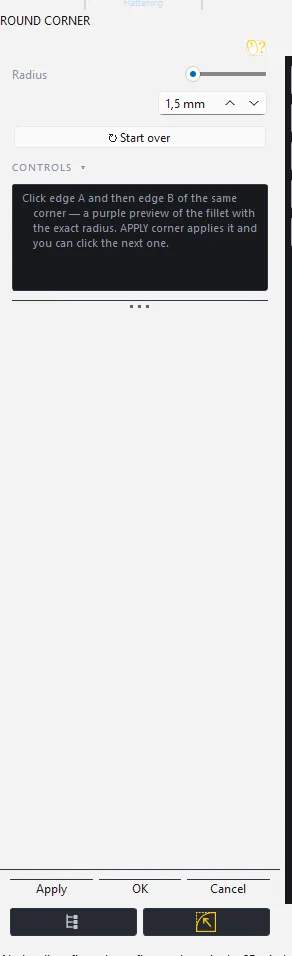
- Set the Radius (or Ctrl + wheel).
- Click edge A and then edge B of the same corner. A purple preview of the rounding appears.
- Apply applies the corner; you can click the next one. ↻ Again discards the corner clicked so far.
Cut
Cut splits a flattened part with a line into two pieces directly in 2D, without going back to 3D.
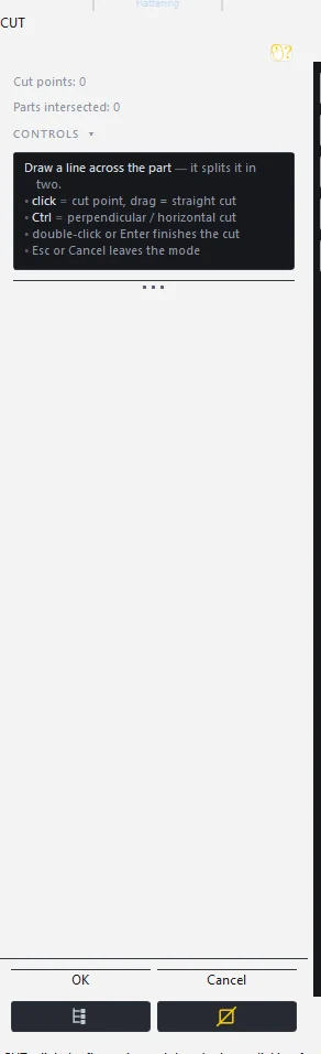
- A click is a cut point, a drag is a straight cut. Ctrl keeps the cut perpendicular or horizontal.
- A double click or Enter finishes the cut, Esc or Cancel discards it.
- The panel shows the number of cut points and how many parts the line crosses.
Canvas
The Canvas is the white work area under the pattern. It represents the material: Width (vertical) is the roll width (default 1490 mm), Length (horizontal) the length of the unrolled piece (default 5000 mm). The dimensions change live, OK confirms, Cancel restores the original ones. Remove work area deletes it from the 2D view. The canvas also works in an empty scene.
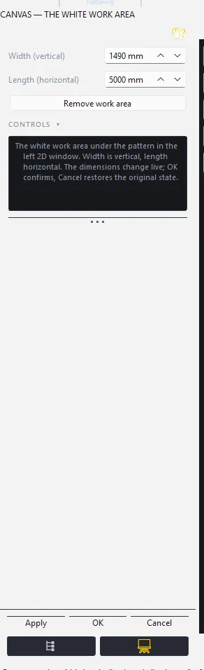
In the PDF export every canvas is one page. When the parts do not fit into the length, Auto-nest creates another canvas below the first one.
Artwork (print)
The Artwork tool places an image (PNG, JPG, BMP, TIFF) on the 3D model and transfers it into the 2D pattern, so the print file fits the part exactly. It works on a single part as well as on a group of parts, where the pattern continues across the seams.
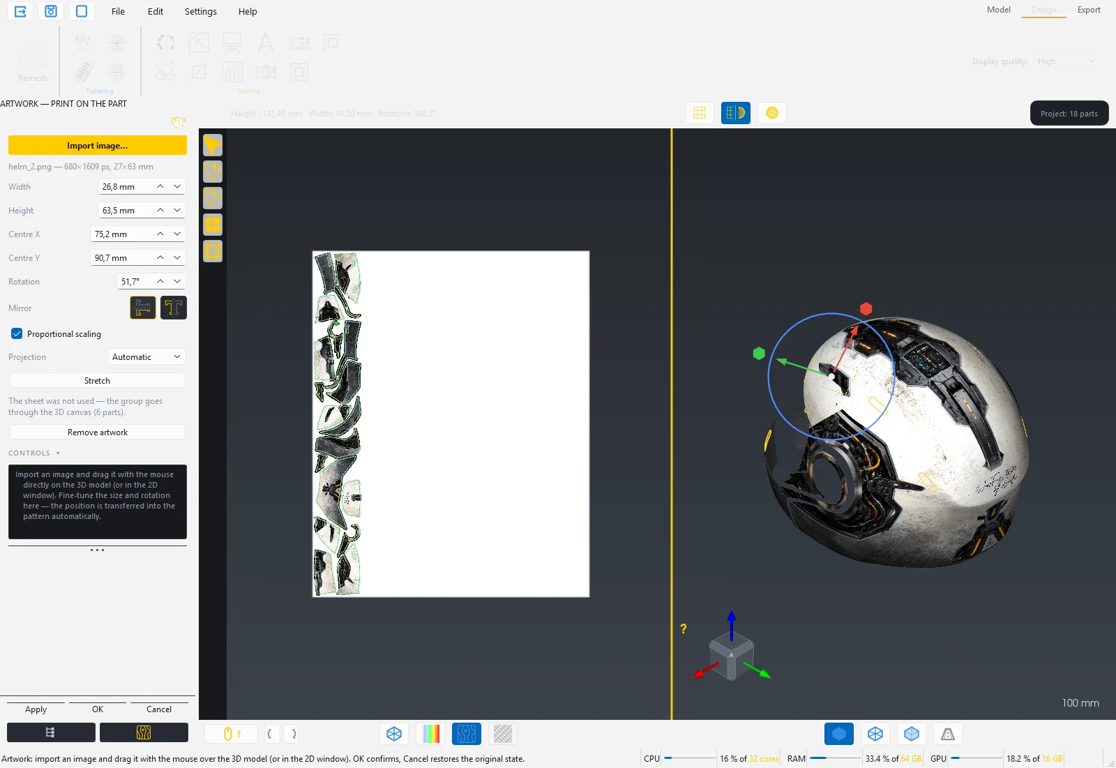
- Select a flattened part and press Artwork. The Artwork display mode switches on.
- Import image… The program accepts a file up to 50 MB and up to 150 MPx (million pixels, e.g. 15 000 × 10 000 px) — the aspect ratio is not limited.
- Grab the image with the mouse directly on the 3D model and drag it into place. Around it is a yellow frame and the gumball: the ball moves freely, the arrows along the axes, the blue circle rotates, the squares change the size.
- Fine-tune the dimensions and position in the panel: Width, Height, Centre X, Centre Y, Rotation, Mirror horizontally and vertically. Proportional scaling keeps the aspect ratio; Ctrl during the drag toggles it.
- OK confirms, Cancel restores the state of the whole group from when the tool was opened.
Several images on one part: every import adds a new layer on top. Change the order of layers in the tree with a right click on the image (Move up, Move down). Remove artwork deletes the active image in all parts of the group. A double click on the image on the 3D model also opens the tool from the Model station.
Projection sets how the image is projected onto a group of parts:
| Option | When |
|---|---|
| Automatic | Uses the sheet if it covers all parts well, otherwise the whole group goes through the 3D canvas. Default. |
| Sheet | Forces a common surface map of the group. The pattern continues across the seams between parts. If it fails, the program shows the reason and the group stays on the canvas. |
| 3D canvas | A planar projection across the whole group; the sheet is not used. |
The Stretch button computes the sheet and stretches the active artwork over it without distortion so that it covers all parts of the group: the image is scaled uniformly (aspect ratio kept) until it covers the whole unfolded shape of the group, and whatever overhangs beyond the parts is not printed. The rotation and mirroring of the layer are kept. The shapes and dimensions of the parts do not change; only which piece of the image is printed on the part changes. The sheet is computed on a group of parts; it makes no sense on a single part. While it computes in the background, the artwork can still be dragged; after the computation the pattern on the seams is aligned. Without artwork the button only computes the sheet.
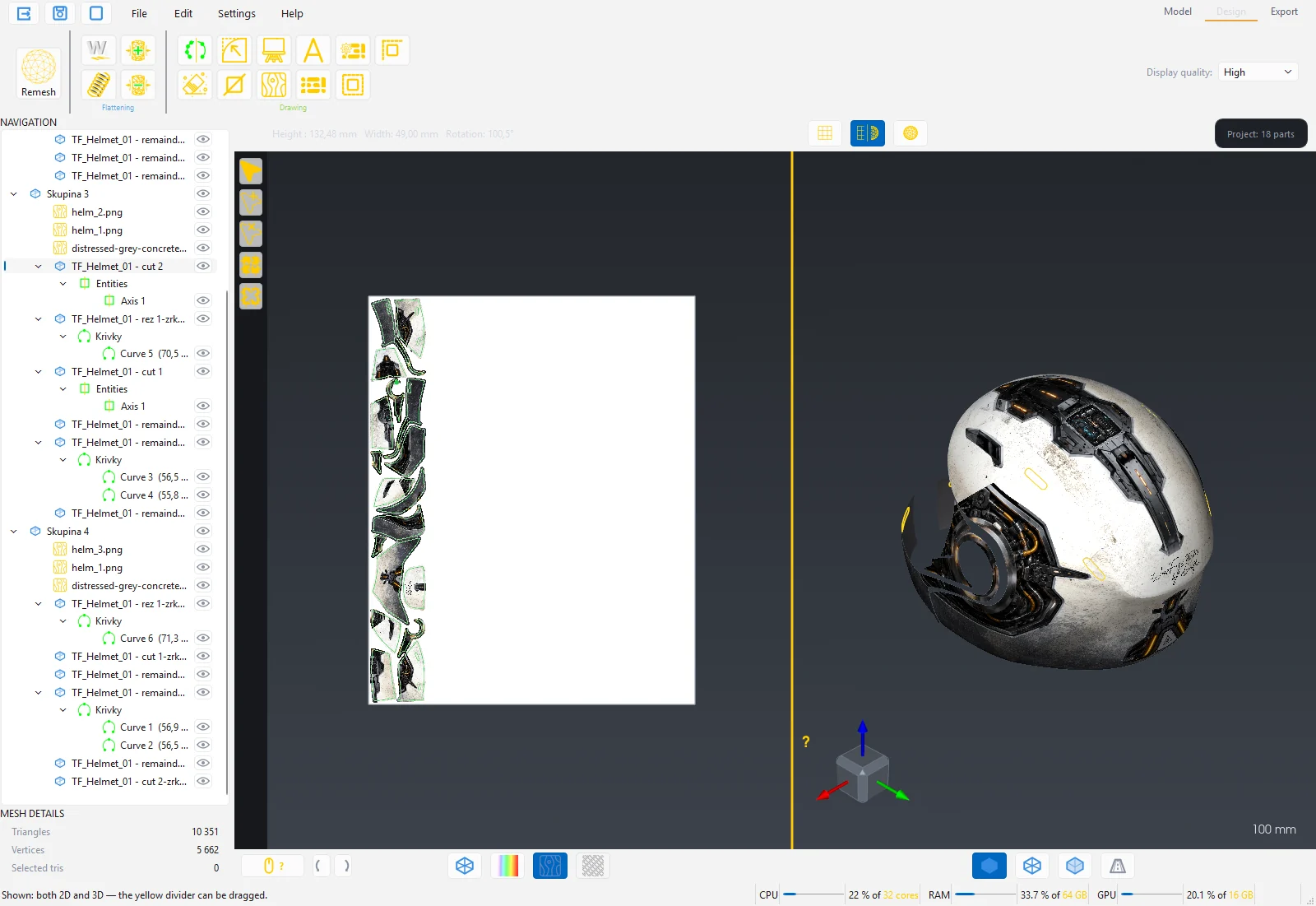
Note: In 2D the artwork is drawn with a 5 mm bleed beyond the cut line. The printer thus has a reserve for trimming. Artwork is not available in the Lite edition.
Text
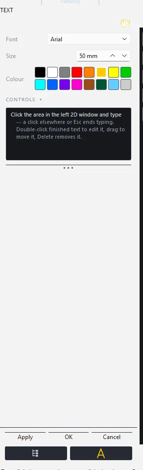
Text writes text on the work area: a click places the text, you type directly, a click elsewhere or Esc ends writing. A double click on a finished text edits it, a drag moves it, Delete deletes it. The panel has Font (a choice of installed, freely usable typefaces), Size in mm and Colour. Texts stay even after Cancel.
Auto-nest
Auto-nest lays the flattened parts out on the work area so that they use as little material as possible.
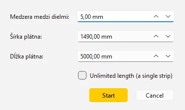
- Select at least 2 flattened, visible parts (or leave all selected).
- Press Auto-nest and set the Gap between parts (default 5 mm), Canvas width and Canvas length. Unlimited length (a single strip) keeps all parts in one strip.
- Start. The status bar reports the number of placed parts, the number of canvases and the utilisation. Parts that did not fit stay where they were.
Auto-nest respects the rotations assigned in the Autonest settings tool. If no part has a rotation, all rotate freely.
Autonest settings
Here you set how Auto-nest may rotate individual parts and what the material is.
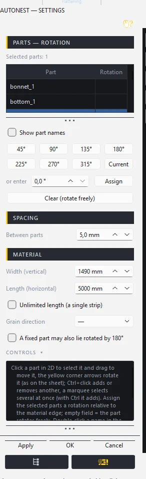
Parts and rotation
- The Part / Rotation table lists the flattened parts. A click on a part in 2D selects it, a drag moves it, the yellow arrows in the corners rotate it. Ctrl+click adds or removes another one, a frame selects several at once. A double click on the name in the table renames the part.
- The buttons 45°, 90°, 135°, 180°, 225°, 270°, 315° assign the selected parts a fixed rotation relative to the material edge. Current takes the rotation the part has in 2D right now. Enter your own value in the field and press Assign.
- Clear (rotate freely) removes the rotation. An empty field means Auto-nest rotates the part freely.
- Show part names writes its name into every part in 2D. It is a preview only; it is not exported.
Spacing: Between parts in mm.
Material
- Width (vertical) and Length (horizontal) of the roll, Unlimited length (a single strip).
- Grain direction: —, 0°, 45°, 90°, 135°. It is display only: hatching appears on the work area and the pattern direction on the 3D model in the Material display mode. Part rotation is always measured from the material edge, not from the grain.
- A fixed part may also lie rotated by 180°: with a material without an oriented pattern, a part with a fixed rotation may also lie turned around; the nesting is denser.
Apply runs Auto-nest with these settings, OK saves the settings, Cancel restores them. Part positions are not restored by Cancel; a manual move and Auto-nest are separate Undo steps.
Tip: Tailors and upholsterers orient themselves by the material edge. With a patterned fabric assign the parts a fixed rotation and set the Grain direction so you can see on the 3D model how the pattern runs across the part.
Contour and Partial contour
Contour (offset) traces the outline of the part outwards or inwards by the given value, for example for a film overlap beyond an edge or for shrinking a part.
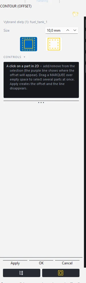
- A click on a part in 2D adds it to the selection and a purple line shows where the offset will be. A frame over the empty area selects several parts.
- Set the Size in mm and the direction Out or In.
- Apply creates the offset and clears the selection; you can select more parts. OK closes, Cancel restores the original outlines.
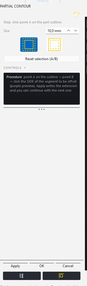
Partial contour makes an overlap only on a segment of the outline: click point A on the outline, point B and then the side of the segment that should be offset. The purple preview shows the result, Apply writes it. Reset selection (A/B) starts over.
2D view modes and layout
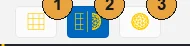
- 2D pattern only.
- 2D and 3D side by side. The yellow splitter between the views can be dragged.
- 3D view only.
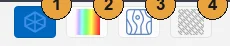
- 2D wireframe mode: outlines only. Default.
- Strain colouring: parts filled according to the strain map, with the legend.
- Artwork display: the print in the 2D pattern and on the 3D model.
- Material display: the grain direction projected onto the 3D model. Active only with a grain direction set in the Autonest settings.
In the Export station there is always 2D only; the program remembers the Design layout and restores it on return.
6 Export station
The Export station saves the finished 2D pattern at 1:1 scale into a file for printing or cutting. The ribbon has three buttons: Export to PDF, Export to DXF and Export to SVG. The window shows only the 2D pattern; the dimensions in the top bar are labelled Width and Length.
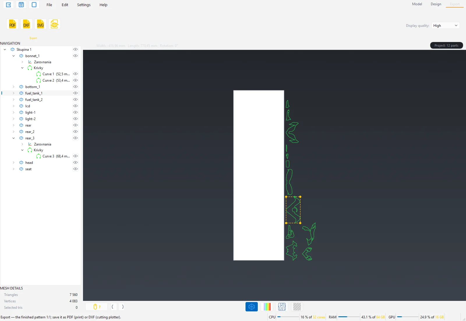
All flattened and visible parts are exported as they lie on the work area. Hide the parts you do not want in the file with the eye icon in the tree. If no part is flattened, the program says so and the export does not start.
| Format | Use | Contents |
|---|---|---|
| Printing artwork with cut contours in the printer's RIP. | Rasterised print, cut lines as the spot colours ThroughCut and CutContour, optionally sewing aids. Every canvas is one page. | |
| DXF | Cutting plotter, CAD, ExactCut. | The CUT layer (outlines) and the KRIVKY layer (marking), units mm, smooth curves. |
| SVG | Graphics programs, web tools, checking. | The CUT and KRIVKY groups, mm 1:1, smooth curves. |
Export to PDF
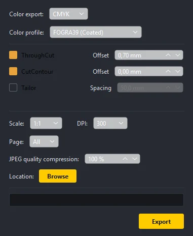
- Color export: CMYK for the printer and RIP (the spot contours stay separate separations), RGB for on-screen preview.
- Color Profil: the ICC profile for converting the artwork colours. For printing in Europe the standard is FOGRA39 (Coated). None is a fast conversion without a profile.
- ThroughCut and its Offset: through-cut, a red hairline with the spot colour ThroughCut. The material is cut all the way through. A positive offset moves the contour outwards from the part, a negative one inwards. Default 0.70 mm.
- CutContour and its Offset: kiss-cut, a magenta hairline with the spot colour CutContour. The outline of the decal; the backing stays. Default 0.00 mm.
- Tailor and Spacing: sewing aids for tailors, see below.
- Scale: 1:1 for printing at real size, 1:10 and 1:20 for a check print.
- DPI: the resolution of the rasterised artwork. 300 dpi is normal large-format printing; higher values enlarge the file.
- Page: every canvas is one PDF page. All exports all canvases.
- JPEG quality compression: 100 % is lossless; below roughly 85 % artefacts may appear on flat areas.
- Location and the Browse button: where the PDF is saved. Without a choice the program asks at export.
- Export starts saving. A bar in the window shows the progress.
The program remembers the options for the next export. The default file name is the name of the first part with the suffix "_strih.pdf". After saving, the status bar reports the colour mode, profile, scale, DPI, number of pages, size, number of cut lines and the file size.
The spot colours in the PDF are named exactly ThroughCut and CutContour, as RIPs such as Roland VersaWorks, Esko or Caldera expect them. The hairline is 0.1 pt so it is not counted into the print.
Warning: PDF export is not available in the Lite edition. In Lite the pattern is exported to DXF or SVG.
Tailor: sewing aids
For upholsterers and tailors who sew the parts together. With Tailor switched on, tick marks appear beyond the trim according to the seams: a 3 mm safety zone, a 5 mm tick, a 2 mm gap. Every fifth tick carries a ball with the seam number; both sides of the same seam have the same number. The ticks are measured along the 3D arc of the seam, not along the 2D outline, so both sides of the seam match.
- Spacing sets the distance between ticks (default 50 mm).
- Switching Tailor on sets ThroughCut to 10 mm and switches CutContour off; switching it off restores the original values.
- Below the row the recommended part spacing for auto-nesting appears, so that the tick zone of each part does not reach into its neighbour. Set this value as the Gap between parts in Auto-nest.
- The aids print in black, not as cutting data; people at the sewing machine should see them.
Export to DXF
Press Export to DXF, choose the file and save. The default name is the part name with the suffix "_strih.dxf".
- Cut outlines are in the CUT layer (green), marking curves in the KRIVKY layer (yellow).
- The coordinates start at the corner of the work area, in millimetres.
- Outlines with smooth curves are saved as SPLINE, the others as LWPOLYLINE.
- Sewing aids are not drawn into DXF; they are only in the PDF.
Open the file in ExactCut or in the plotter software. The status bar reports the number of outlines and curves.
Export to SVG
Export to SVG saves the same pattern as a vector file in mm 1:1 with the CUT and KRIVKY groups and smooth curves. Useful for checking in a graphics program or for tools that do not read DXF.
Export from the context menu
A right click on a part in the tree offers Export 2D pattern (DXF), (SVG) and (PDF 1:1) from any station.
Exporting a 3D part
File → Export… (STL, OBJ) or Ctrl+E saves the current 3D part as STL, OBJ or PLY, for example a cleaned and repaired scan for another program. The selected part is exported, not the whole scene.
Exporting IGES curves
Curves from the Curve tool (spline, polyline, boundaries) can be saved as IGES for CAD: right click on the curve in the tree → Export as IGES. With several selected curves, export into a single file is available. The file is in millimetres.
The .wfg project
File → Save (Ctrl+S) saves the whole scene into a .wfg project: all parts, groups, entities, flattenings, strain maps, artwork and the work area. The project opens via Open or by double-clicking the file in Explorer.
- The project size is given by the vertex count and the artwork, from a few MB for small parts to hundreds of MB for a whole car.
- The program saves safely: the new version is written alongside, the previous one stays as a backup with the .bak extension until the new file is complete.
- Saving is not possible while a tool panel is open. Close it first with Apply or Cancel.
- Saving is always allowed, even when the tools are locked by the licence.
Tip: Save the project after every major step (after mesh repair, after Cut with a curve, after flattening). With large scans you will not lose hours of work.
7 Workflows from start to finish
Three typical jobs step by step. Each workflow uses the tools from the previous chapters, arranged here in the order they follow in the workshop.
Printed helmet to PDF
Goal: a printed film for a helmet, split into parts with seams, with cut contours for the printer's RIP.
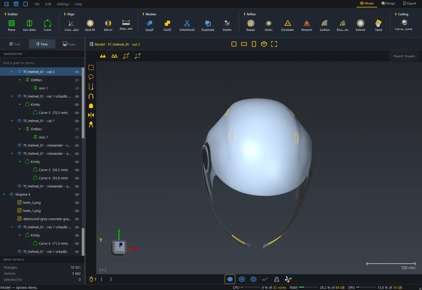
- Open the scan of the helmet (STL). Check the triangle count below the tree.
- Repair mesh: keep the default categories, switch on Highlight errors on the mesh, press Apply and OK.
- Fill holes: a helmet scan often has openings at the visor and along the edge. A click on the boundary fills the hole, OK saves.
- Cut with a curve: draw the curves where the seams of the film will be. A helmet typically splits into the crown, two sides and the back. Close the curves or connect them to the outline. Apply shows the coloured preview, OK creates the layers.
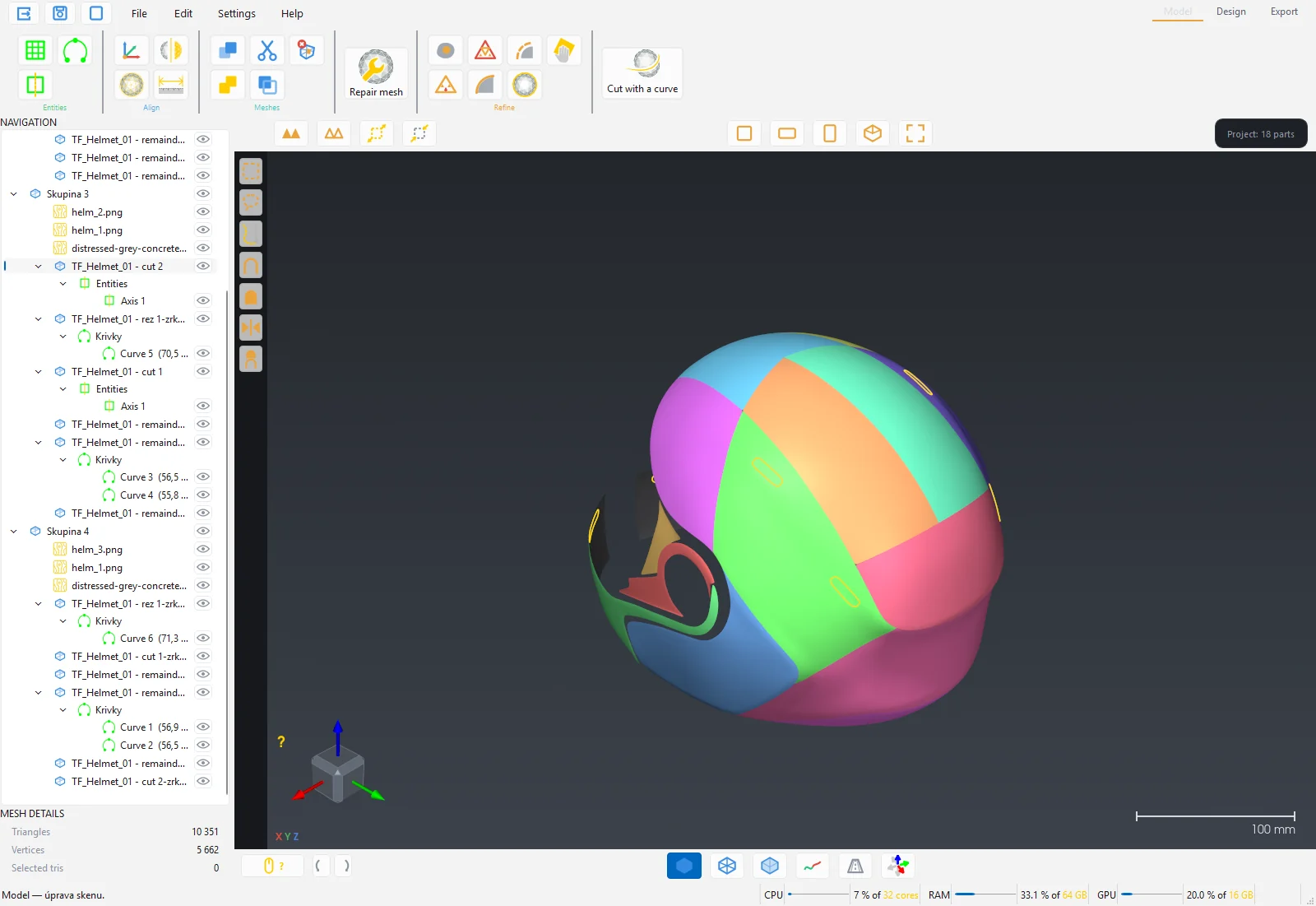
- Put the parts into a group: select them in the tree with Ctrl+click, right click → Create group. The group allows one artwork across all parts.
- Switch to Design. Click the group (all members are selected) and press Remesh, Start, OK.
- Flattening on the selected group. The parts appear in 2D below the work area.
- Switch on Strain colouring and check the map. Red or black areas mean the part has to be cut differently in Model.
- Artwork: Import image, drag it onto the helmet in 3D. Projection Automatic or Sheet so that the pattern continues across the seams. OK.
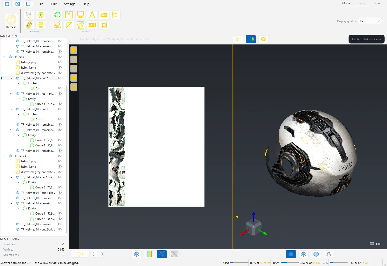
- Auto-nest: lay the parts out on the work area according to the roll width.
- Switch to Export → Export to PDF: CMYK, FOGRA39, ThroughCut 0.7 mm, scale 1:1, 300 dpi, Export.
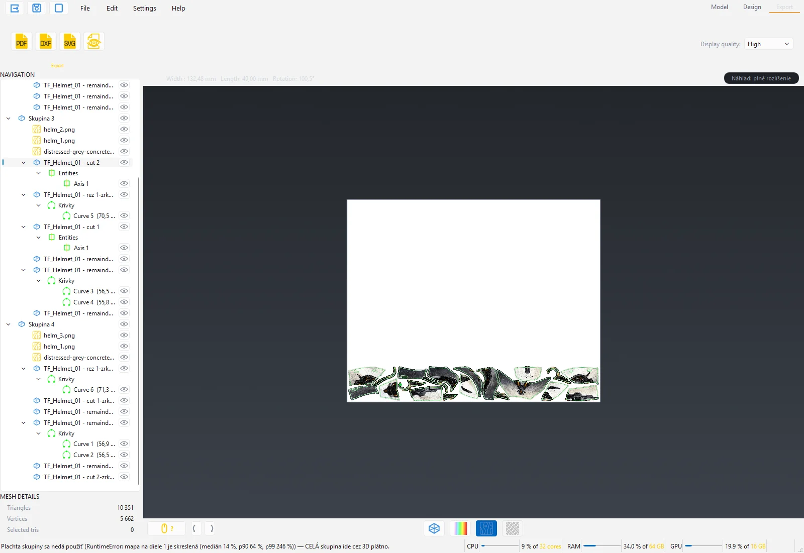
- Save the project (Ctrl+S) for a possible repeat production.
Motorcycle without print to DXF for a plotter
Goal: clear PPF film for the tank and fairing of a motorcycle, cut on a plotter.
- Open the scan. If the motorcycle was scanned as one piece, separate the parts (tank, fairing, seat, lights) with Cut with a curve and name them in the tree (F2).
- Check Repair mesh on every part and smooth jagged edges with Smooth boundaries.
- Where the film should go around the edge of the part, use Extend boundaries by 5 to 10 mm.
- In Design select all parts, Remesh and Flattening.
- Look at the strain map. The tank is domed; with a large stretch cut it in Model into two halves with the seam in the middle.
- Refine the outline: Point reduction (Automatic reduction), Round corner on sharp corners that would lift during application.
- On parts where the film is tucked under, add Contour Out by 3 mm.
- Autonest settings: roll width, gap 5 mm, rotation free. Apply.
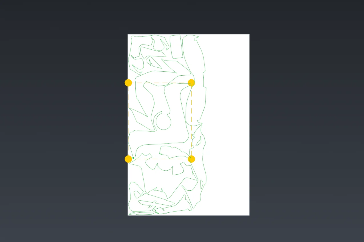
- Export → Export to DXF. Open the file in ExactCut or in the plotter software; the outlines are in the CUT layer.
Composite bonnet with grain direction
Goal: the reinforcement pattern (carbon, glass) for laminating a van bonnet with control of the fibre direction.
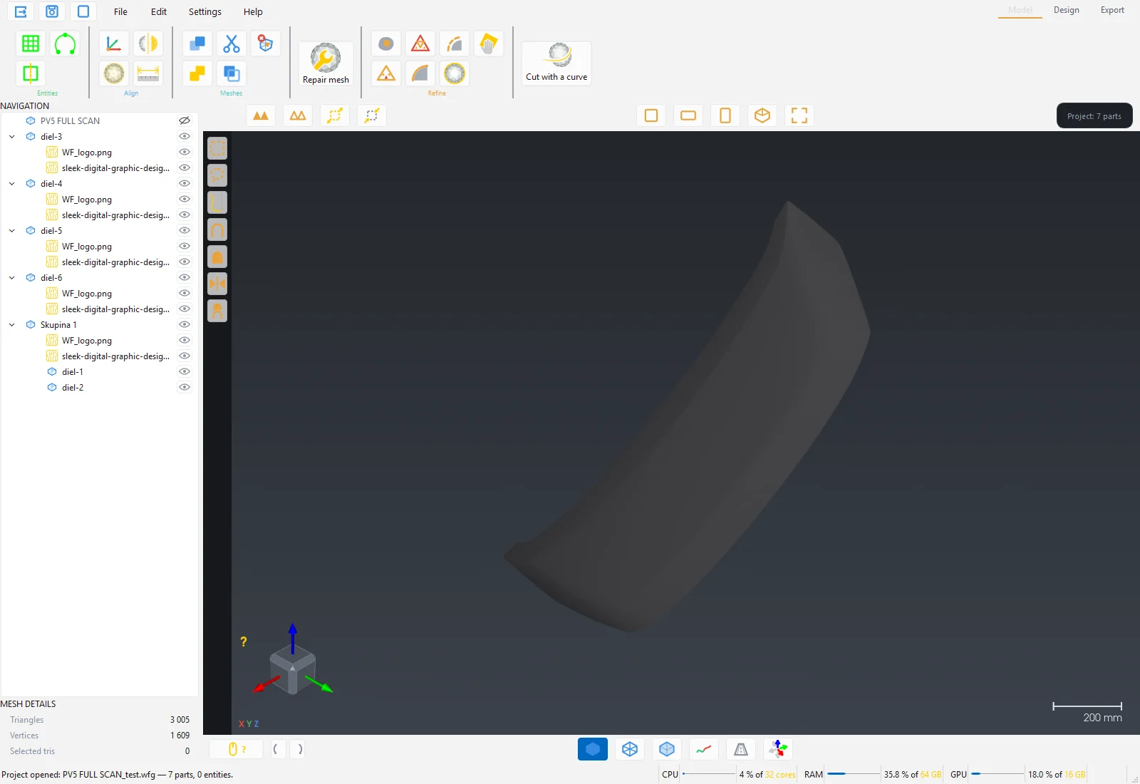
- Open the bonnet scan. If the scan also contains the inner side of the panel, mark the outer surface with Select a curved area (with a larger edge angle) and Duplicate selection into a new layer. Continue with that layer.
- Repair mesh and Fill holes.
- If the bonnet has a crease that cannot be unfolded in one piece, separate it with Cut with a curve. The top surface stays as one part.
- Design: Remesh with a higher vertex count (for example 8000), Flattening.
- Spring with the reinforcement material (import your own material with the moduli in the winding and cross directions, Orthotropic mode).
- Autonest settings: set the Grain direction (0°, 45° or 90°) and assign the part a fixed rotation relative to the material edge. Switch on Material display and check on the 3D model how the fibre runs across the bonnet.
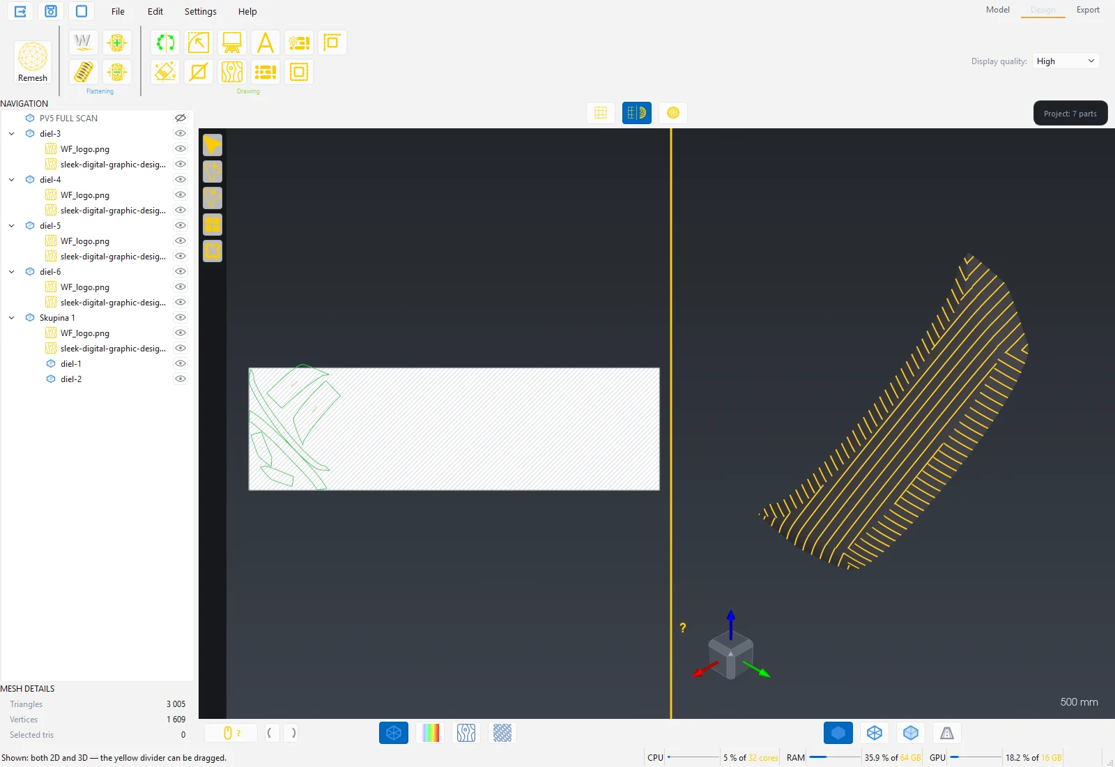
- Apply in Autonest settings lays the parts out with the fixed rotation.
- Export to DXF for the cutting plotter or Export to PDF 1:1 for a printed template.
Tip: For multi-layer laminating save the project and for each layer change only the Grain direction and the part rotation; the pattern stays the same.
8 Troubleshooting
The most common situations and what to do about them. If the fix does not help, write to podpora@draftex.sk and include the program version (Help → Support), the computer code (Settings → Licence) and the file where the problem occurs.
Licence and start-up
"The licence server is unreachable." at start
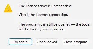
The program could not connect to the licence server. It offers Try again, Open locked (tools locked, saving works) and Close program. Proceed in this order:
- Check that the computer has internet and that the browser opens https://wrapforge.sk.
- Antivirus or firewall (most often ESET) may block the connection for this program alone, even though the browser works. Add WrapForge to the allowed applications for outgoing connections on port 443.
- On Windows 10 without updates the root certificate the server trusts may be missing. Install the Windows updates and start the program again.
- Company network with a proxy: the program uses the Windows proxy setting. Check it in Windows Settings → Network & Internet → Proxy.
- If nothing helps, support sends you a diagnostic tool that prints the exact cause. Run it under the same Windows user as the program and send the output back.
"The licence seat is in use by another computer."
All seats of the licence are taken. Either close the program on the other computer or press Take over the seat. The other computer gets 30 seconds to save its work and then locks. If the seat is held by a computer with an offline loan, it cannot be taken over until the loan ends or is returned.
Yellow bar "The connection to the licence server is interrupted"
An internet outage during work. The program keeps running for 15 minutes; the bar shows a countdown. Save your work and press Try again when the connection is back. After the time runs out the tools lock; saving remains available.
"WrapForge is already running on this computer."
The program runs only once. Switch to the open window. If you do not see it, look in the taskbar or the Task Manager to see whether the previous instance is still closing.
"This function is not in the Lite edition."
PDF export and artwork are in the Standard and Pro editions. Export the pattern to DXF or SVG, or contact support about changing the edition.
Flattening and mesh
"The part has not been through remesh yet."
Flattening accepts only parts after Remesh. Run Remesh in the Design station and then Flattening.
Remesh fails at every vertex count
The mesh is damaged. In the Model station run Repair mesh with all categories, possibly Fill holes. If the part contains two scan layers on top of each other (outer and inner side), separate the outer one with Select a curved area and Duplicate selection.
"The mesh cannot be prepared for flattening (tunnel / non-manifold even after clean-up)"
The part has the shape of a tube or contains non-manifold spots (an edge with three faces). Cut it with Cut with a curve so that every piece is an open surface, and run Repair mesh.
Dark crosses in the 2D pattern (flipped polygons)
The part is too curved for one piece. Go back to Model, split it into several parts and repeat Remesh and Flattening. Spring and Tension do not work with flipped polygons.
Red or black areas in the strain map
The film would have to stretch or compress more than it can at that point. Either change the seam position (cut the part differently), or account for stretching during application and use Tension + in the stretching direction.
The outline after flattening looks simplified, small creases are missing
Increase the Target vertex count in Remesh and repeat Remesh and Flattening.
The cut curve is red and Apply does nothing
A red curve has a free end. Connect it to the outline of the part or to another curve (a double click there ends the line), or close the curve with a click on the first point.
Selection and display
Rectangle selection also selects the back side of the scan
Switch off Through in the left bar; the selection then takes only visible triangles.
Brush or rectangle selection is dotted, incomplete
On a very dense scan with several layers the program selects only the visible surface. Use Grow the selection (+) or Select a curved area, which selects a connected surface up to the edges.
The model does not rotate with the left button
This is intentional: the right button rotates the view, the left one is for the tools. The controls overview is under the yellow button with the question mark in the bottom bar.
The artwork looks blurred in 3D
Raise Display quality in the ribbon to High or Realistic. The setting has no effect on the print export; the PDF is always rendered at the chosen DPI.
Performance and memory
Loading a scan takes long or the program reports a lack of memory
When loading, a scan asks for 8 to 12 times its file size in memory. Close the parts you do not need, or split the scan first in the scanner software. Undo keeps a copy of the mesh; after large operations save the project and open it again, memory is freed.
Sand the surface reports the limit of 8 million triangles
Cut or decimate the part first. Selections have no limit; you can sand just a selected area.
The program "stays slow" after stopping a long computation
Press Stop or End in the window with the bar and wait until the window closes. The computation only ends then.
Export
"No flattened part to export."
Only flattened and visible parts are exported. Check the eye in the tree and whether the part has been through Flattening.
The printer's RIP does not see the cut contours
The contours are the spot colours ThroughCut and CutContour as 0.1 pt hairlines. In the RIP (VersaWorks, Caldera, Esko) set these spot colours to be treated as cutting data. Export in CMYK; in RGB no spot colours are created.
The plotter cuts the outlines inaccurately, arcs are angular
The DXF contains smooth SPLINE curves. If the plotter software does not read SPLINE, import the DXF into ExactCut or use SVG.
Update
The update failed
The program continues in the old version and repeats the offer at the next start. The most common cause is a refused Windows administrator consent: without it the program files cannot be overwritten. If the failure persists, get the full installer from support and run it by hand.